Activity Stream
Posts Activity Stream
-
-
Nice, I don't think I've seen any Avids in the pictures I've seen online of Valdez. Hope to make it to that eventually. My wife's sister and her family live in Fairbanks, so we might have to visit...
-
It sounds like the standard upgrades (steel gussets or plywood) have proved to be adequate. I wasn't happy with the way the gussets in my plane look (looks like someone did a rough job with a mig welder, and blew at least a couple of holes in the top tube), so I'm going to replace the whole truss. I don't know what is normal for the gussets, but mine has .040". They are pretty heavy. I modeled the stock truss on the computer, and then added the gussets. I don't remember the exact numbers, but they basically doubled the weight of the truss. I'm hoping to keep the weight closer the the stock weight.
As far as pilot skill goes, I'm sure I'll put the plane to the test. I just got back into flying recently after about 16 years away, and it wasn't too pretty at first. I'm a low time pilot to start with, and on top of that, I need to learn to fly a TD!
-
no its for 2 plates and two additional calipers and plumbing. you then mount two calipers per plate and plumb them together to give you double pucks on each side.
-
By adding the plates to the side of the fuse, and the gussets on the truss, I think you will have a winner. I have smacked mine down pretty hard and hit some snow drifts during flat light, bent a few sets of axles, and have yet to bend the plane or the gear legs. I think most stress is put o the plane when guys are first learning to fly them. They are a VERY draggy plane so if you round out the flare at 10' and wait for it settle in like a cessna, your gonna end up landing it 8' off the ground.. the drop and plop method only works once or twice before its back to the shop for a fuse rebuild
 I know a lot of guys got it beat into their heads by brand new instructors that you shouldnt have to touch the throttle after your turn to base if you fly the right approach.. well that may be in a 172, but it aint gonna work in an Avid or KF. Too much drag and the slightest wind gust will put you short of the runway. Elevator controls speed, power controls rate of decent. 99% of my landings are probly around 4200 RPM until the tires are inches off the runway. I think I jockey the throttle more than I do the stick during landings adding bursts of power here and there to keep the site picture I want of the runway. The only time I have not done this was when I had a total engine out, and when I had it overheat and pulled it back to idle at 3000' and dove for the runway. That time I was on skis and had 4000'X 500' to get it down and stopped and I used a VERY aggressive slip to get it to come down even faster than normal (I had the VSI pegged at 55 MPH and the GPS was showing around 3200 FPM decent)
-
Funny Pics
in Jokes
-
Thanks for all the pictures you share on here. It's always to cool to see the stuff you guys get to do up there. The scenery is really pretty too.
-
That's kind of what I was thinking, but I just didn't know what kind of numbers are realistic. That's where feedback from you guys that have lots of hours in these planes is so helpful. You know what kind of a beating they can normally take.
If I use 500 FPM, I should be able to figure out the rest by calculating gear stroke, acceleration, and then force. From there the stress calculations are fairly simple. The 6" rock is a good thought too. I think I'll assume that if you're hitting those, you have some tires that can help out a little.
I have thought about beefing up the rear attach point though. Extending the gear leg length puts more force back there (especially when you hit big rocks). Moving the attach point back would help, but means adding more weight to create a new reinforced point on the fuselage. Adding more reinforcement to the existing point is probably more practical. Of course, I don't want to outsmart myself and make gear that's so overbuilt it just bends up the rest of the airplane

-
Leni,
That $260 is for 2 plates? 1 for each side? Why so expensive? With the cost of machining equipment slowly coming down why do we have to pay so much for parts like these? Is it still liability? Shouldn't the "Experimental" part of our planes get rid of a lot of the liability?
I'm not slamming Matco, it is all aviation related companies. Sorry, rant is over.
Do you just tee the line into the first brake over to the second? Not a bad idea, I guess it would be a little more bulky of an install.
-
I am jealous.. I hope to be there next year with the Avid.. and the big engine... I may not be able to land as short as some of the cubs, but I bet takeoff will make up for it
-
to calculate the stress think of the plane at gross weight, you just hit a sinker on landing and smacked down at 500 FPM and hit a 6" rock
Or put 26 or 29" bushwheels on it to take the sink and the rock out of the equation since they absorb 90% of the impact not your seat truss or fuse.
1 person likes this -
I think the MCMC4GH master would work better on the Avids with the updated pedals as it is shorter than the 4D master. But you still have to deal with the rudder bar issue and slot the bottom of the master or move one mount tab on each of the rudder bars.
http://www.matcomfg.com/MasterCylinders-tp2-5.html
Link the Matco master cylinder page
-
I talked to Matco yesterday and George got a good laugh out of me trying to stop the 30" airstreaks with the single pucks. for 260 bucks they will send you a kit with new backing plates that allow you to put two single puck calipers on each wheel like the highlander has. I figured while I am at it I will put new pads on my existing calipers and see how that does. Just for shits and grins I plan on putting a pressure gauge on the end of one of the hoses just to confirm that I am getting enough pressure to the calipers with the updated pedals and the MCMC4D masters.
I filled the brakes from the caliper to the reservoir so there is no air in the system and the masters are nice and tight. I was pushing on the pedals so hard that I hobbled around for 3 days after the flight due to a pulled hamstring
Using the MCMC4D masters I had to make some mods since they wont bolt on to the older style rudder bar on the Avids. I don't have any pictures of it but I will try to draw something up to show what I had to do to make them fit.
Edit: added drawing to help muddy the waters on installing the MCMC4D masters.
With the updated pedals having a lower mount point to get the correct leverage, I had to modify the clevis on the top of the master to make it as short as possible. I also had to cut a few threads off the shaft of the master so it would not hit on the pedal mounting tab. I ground off the corners of the pedal mount tab to give me more clearance as well. The base of the master is rounded with holes drilled in it 90° apart. I used a hack saw and cut down the center of the master to give me slot to slip over the mount tab on the rudder bar as the mount tabs on the rudder bar are too close together to just bolt the master on to it. I had to make the slot about 1/4" deeper in the master as the hole drilled in the base of the master was flush with the bottom of the slot.
I will see if I can pull up a stock picture showing the base of the master so you can get a better visual on what I had to do. It would be easiest to just cut one of the tabs off the rudder bar and move it out and not have to modify the master, but if its already in a flying plane and you don't want to pull out the rudder bar, modifying the master is your only choice.
-
I was told that the belts should be changed every 500 hours, or as needed.
Thanks for posting the good info Randy.
EDMO
-
how large is the picture file your trying to post? what is the error you get when trying to post pictures. Some internet providers will time you out if its taking too long to upload a picture or file. If your on DSL this shouldn't happen, but when I used to be on dial up at work it would do it too me all the time.
-
Doug,
After making the comment about spending big $$ for Rotax parts, I felt badly about what I had said - I was thinking experimental, where you can innovate without problems - then I realized that you may have been talking about the factory-built LSA, and you may not have the options of variations on it.
I still like the dual Facet electric pumps, and you can order them with check valves in either or both directions - I would opt for the check valve to prevent reverse flow, but none to check gravity flow.
For 27 years as a toolmaker, I cut, bent, welded, made, about every crazy design tool that would do the job - Leni had a good suggestion about cutting, bending, a wrench and welding a socket on it - I have done that ten thousand times. Low-hydrogen rod, and no quench works good for an arc welder, and either welding or brazing with OA works good too. Just grind the chrome off first. You probably know all this, but someone else might not.
EDMO
1 person likes this -
-
Nice! I never got a chance to get out and do anything other than 4 laps around the Soldotna airport last time home after I got the new shoes on my bird. I think I have all the moving done now and I will be able to get some fun flying in when I get back in two weeks. My next time off is the last chance I will have to fly till I get back from the Houston, New Orleans, work trip from May 27th till July 15th... once again, 2/3rds of the summer is shot for me...
-
Any chance you can heat up and bend an 11mm wrench then weld a socket to the end to hook to the tq wrench? You could then to the math to figure out the additional leverage you now have. One thing I have done i nthe past on problem bolts ot to use the tq wrench on a bolt I can get to, then put an end wrench on same bolt and "feel" the amount of pressure I have to put on the wrench to get it to slightly move. I then use that "feel" to tq the other bolts. If you really want to be anal about it, you can use a digital fishing scale on the end of the wrench and use it to pull to see how much pressure you have to put on it to achieve the desired tq.
As far as electric pumps, they are pretty damn steady in the pressure they put out, and you can always jump a pressure regulator in line and set it at EXACTLY the pressure you want at the carb. I had to do this on my snogo as the Arctic cats like 41-42 PSI on the fuel injection and from the factory they were running around 48. This led me to have shit for power and I left a nice big black streak in the snow when ever I would stop for a moment then take off again. I installed the pressure regulator and set it and have not had any issues in over 6000 very hard ridden miles.
-
Never thought about doing that Leni. In fact, I've never even heard or read about anyone else removing the mechanical pump on a 912 either. Which makes me wonder if something specific precludes the use of electric pumps only. I do know the 912UL and ULS both seem very finicky regarding fuel pressure, that was one reason I asked in another thread if anyone using the MGL E-1 had wired in a fuel pressure sender. That fluctuating fuel pressure issue can usually be traced to a failing pump or the fuel system plumbing. Other than the recent fuel pump weep issue I experienced, I've had no problem with fuel pressure with my 80hp 912 in the KF4 (at least, that I know of) but I do want to monitor it now. Leaning toward installing a FACET backup in this plane. Also, a low fuel warning light is on the To-Do List, probably when I replace the current high mount header with a behind the seat aluminum header tank. IMHO, that location makes for better plumbing and provides a tank fitting for the low fuel sensor.
There are notes in my Aerotrek log that fuel pressure has been problematic. It had one replacement pump even before the Rotax SB. No engine outs but widely fluctuating pressure and several instances where the needle went to zero. That plane has a 912ULS and is plumbed with a return line to the header tank so I think the replacement pump was likely a bad pump too. I already installed another new (pre-SB) pump that came with the plane, but haven't tested yet. In any event, I took advantage of the special Rotax pricing after the SB and bought two, so I still have one new, improved spare pump sitting on the parts shelf if that one proves to be problematic too.
Ed- I am aware of the issues requiring a conversion calculation when torquing on an angle, or if an extension points straight out of the torque wrench. However, if you attach the crowsfoot at a 90* degree angle to the torque wrench, then bolt torque equals the wrench torque setting regardless of how long the crowsfoot is. So if I can actually get to the bolt with the crowsfoot at exactly 90* degrees, no such conversion calculations are necessary. I can't use the 'standard' short crowsfoot to get to the bolts, so I'm looking for a long 11mm crowsfoot to fit either a 3/8" or 1/2" torque wrench head.
-
-
I didn't know the plywood reinforcement was enough for the WIB gear. That's good to know. Earlier in this thread, IFMT suggested a beefed up truss like the one he bought from Airdale because he had bent his original. I wonder how his replacement truss compares to the plywood add on.
I did some calculations on some different truss designs with different tubing sizes. The problem is that I don't know how much force the truss should be able to handle (how hard of a landing to design for). The best I could do was try to reverse engineer the existing truss, and then design a new one that can handle more force at the bungees. I hope I can at least proportion the members in the truss to match each other so that I'm minimizing the weight. I guess I'm just over thinking this. Thanks for the information though.
-
Ron,
I tried to put mine where I thought they were least likely to be damaged but on top might be better if you can make it work. The Matco calipers are on the inside of the disc so don't stick out where they can scrape on the tire like the Cleveland calipers. Sounds like Chris has the best advice for those.
-
I have a RAM dual ignition on mine. The first one I got from them did not want to run on one of the ignitions so I sent it back and the second one has worked flawlessly with no issues. I never can remember if it is the Nippon denso or the Hitachi ditributor though. (I have to sketch the distributor cap so I can make sure I get the correct parts). It has dual ignition pickups in the distributor and goes to dual coils then to a coil joiner. I only run one ignition at a time since prolonged running of both ignitions will overheat the coil joiner; but it gives you a backup ignition to switch to if the primary fails. The Stratus secondary ignition runs from a second trigger on the crank and uses the dual coils and coil joiner so still operated one at a time. Both are run through the distributor so single system from the distributor to the plugs.
Stratus recommends changing the distributor cap and rotor every 300 hours, the plugs every 200 hours and the plug wires every 1500 hours. I am sure it is very much on the conservative side since I just changed my cap and rotor with about 320 hours on it and looked almost new. Jack just helped me pull the redrive apart last weekend and repack the drive bearings, everything was in great shape; smooth and tight. The belt is recommended to be changed at 300 hours but it still looks nearly new with no visible wear. I decided I will go a little longer with it and just keep inspecting it closely.
Mine turns 4800 rpm on takeoff with the stratus redrive 2.2:1 with a 72" IVO prop at flat pitch if that info is of any use.
-
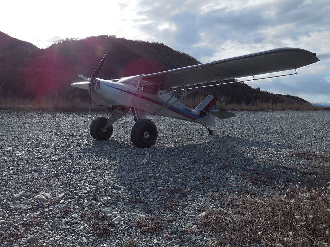
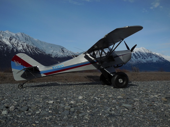
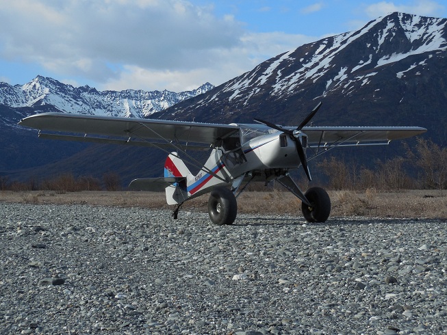
I always enjoy changing from wheels to skis atthe start of winter and skis to wheels in the spring. Just got back on wheels last weekend and had a chance to get out and play on the gravel for a couple of hours. The landings orientation is a bit different so had to clean some rust off. This is the perfect time when the river is low to land in places normally under water.
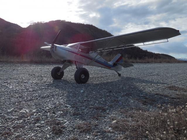
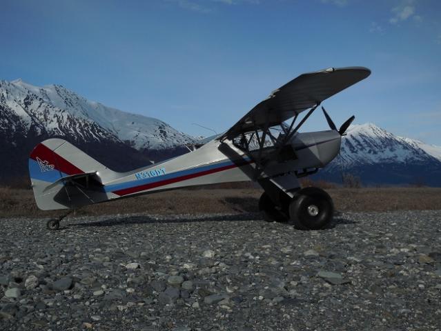
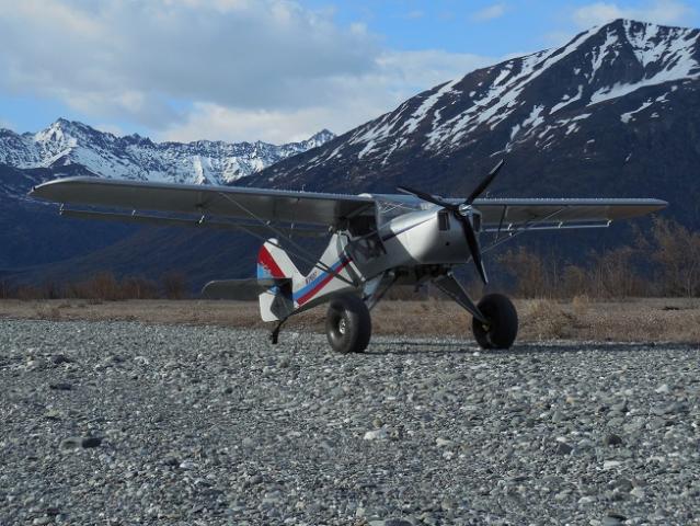 1 person likes this
.jpg.4b33961872f0355d5e844f76433b74f3.thumb.jpg.9e3553a256b702f9ca668642dbf33570.jpg)

How to Check the Fuel Flow using the ‘Bleed Off’ Method
in Technical tasks
dholly
Posted
One way to measure fuel flow thru the mechanical fuel pump...
fuel%20flow%20check.pdf