flywise
Contributing Member-
Content count
374 -
Joined
-
Last visited
Posts posted by flywise
-
-
Hey Jim one alternative is to order the Kool prop in Canada....same factory than Luga / NRprop etc
The company is called airtrikes and the boss is called Vassili, a good guy.
http://www.airtrikes.net/propellers.shtml
-
Please give us MUCH more info please & photos
-
Not meaning to sound offensive Laurent, but one of us misunderstood the question. You have me wondering if it was me. I understood him to mean that if the wing is off, and he ran a straight rod down through the rear wing spar attachment point on the fuselage, it didn't line up with the lift strut attachment hole at the bottom of the fuselage. I've been wrong before though, so it won't be a new experience for me. :-) JImChuk
Hey good catch Jim....should have drunk a second coffee this morning HaHaHa
1 person likes this -
Hi everyone,
I have done a search on here but couldn't find an answer so I thought I'd post my question here and see how I go.
While looking at my KF2 fuselage I decided to measure and check everything.
One thing I noticed is that the LH rear spar attachment point does not aim exactly at the centre of the LH lift strut bolt.
The right one lines up perfectly.
I double checked with a long straight round 5/16 bar pushed through the little tubes on the ends of the rear carry through tube and the LH one likes to aim just half a holes worth forward of the lift strut bolt hole where the RH one easilly lines up dead centre.
So..
Does this mean I have a problem ?
Will this mean that the LH lift strut will be exposed to bending/ stress due to the point that the wing pivots back is not exactly in line with the point that the lift strut pivots back ?
Or am I worrying about nothing ?
I'm quite prepared to remove all 4 little tubes (one is shagged anyhow) and make new ones, put them in a square jig and weld them in, but if I do weld them in are they exactly vertical as std ?
Cheers.
Skelly.
This might be due to the LH wing incidence you can adjust on the LH strut. Once adjusted, the wing may be under some tension and the holes don't line up perfectly....
You can try to install the wing/strut with the lower bolt and only one upper bolt and then adjust the adjustable eye bolt to line up with the remaining bolt hole.
Hope this makes sense, Laurent
-
Hey guys, I would like to know if there is a difference folding the wings after installing the F7a upgrade?? More/less of a gap between the flaperons ?
1 person likes this -
Hey Jim, on that subject I find these guys showing how to with pictures quite helpfull. The only thing I know is that the thread is fine thread Metric 46mm
http://www.aerofixaviation.co.uk/rotax912/rotax-912uls-part-10-flywheel-removal.shtml
Also on the german ebay you can order the puller for about 75 usd
-
Thanks Laurent, you mention stator coils, and maybe I'm thinking wrong, (not the first time) but do you mean trigger coils? In my mind, I thinking the stator coils are what do the charging. Which I've wondered about as well. I can't get the tach on my MGL engine monitor to function correctly either and it does read pulses off the charging system. I wouldn't have thought the charging system should make it run poorly, that's the ignition systems fault if my problem is electrical. At least that's what seems right to me. Then again, there is no telling what little tricks Rotax had up their sleeve just to mess with people like me. :-)... I switched the modules and coils from the other engine today, and no better. Even rigged up a gravity feed fuel tank, and that did nothing to improve things. I pulled a cylinder off the spare engine to day to have a look and see if there is any evidence of corrosion inside. Looked perfect, cam lobes were nice and shiney. Unfortunatly when I was putting the cylinder back on, I cracked an oil ring, so there goes another holdup. Plus about $65 after shipping as well. So now I have the spare engine sitting on a cart, and I'll pull the engine off that doesn't want to run smooth and let it take a rest. Before I take a sledge hammer to it.... The saga continues..... JImChuk
PS See Allen, I told you we were crazy.... Who in their right mind would put themselves through this and come back for more?
Hey Jim,
I can feel what you're going through...I nearly lost my mind when I did have my rough running..
Anyhow when you get it going you'll forget the hard time troubleshooting. One thing for sure, you will know your engine inside-out:)
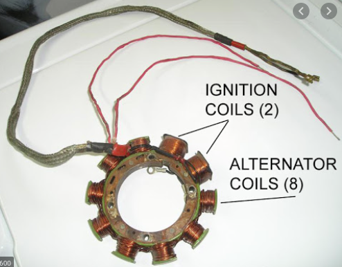
Concerning the coils....you have 8 coils producing electric current for your aircraft (250W) and then you have an additional 2 'ignition' coils producing electricity (unregulated AC) to power each your ignition modules (that way your engine ignition has always power). These are the coils you have to check. Also note the two red wires, they are the ones feeding your modules. Also check these wires as they were a problem / shorting out on some harness against the shielding (intermittent problem). So when you check your two coils through the red wires, wiggle the harness around and check continuity at the same time. Hope that helps,
Keep going..
 2 people like this
 -
Hey Jim,
talking about the grounds...forgot to tell you about the importance of the ignition modules ground wire being 100% grounded. I had a ground wire fitted to a tab on my engine mount and found that the engine mount to airframe ground had some resistance (my engine mount/frame is powder coated), Try and pull a ground wire directly from your batt. neg. to see if things improve. Also the earlier 912 engines had wires shorting in the braided sleeve going to the coils which was an intermittent fault sometimes not powering one module or the other. Also make sure your stator coils are good (measure impedance through the ign module connector)
I am sure you already know, but all these items have a service letter or service bulletin you can find @ https://www.rotax-owner.com/en/support-topmenu/service-bulletins . your solution to your problem might be somewhere else in this long list....
Laurent
-
Yes please advise where to find the used drone engines, that would be cool and hopefully less expensive.
Last time there was one on Barnstormers with a few hundred Hrs for 4K. There is no specific place to find them, you just have to keep looking.
1 person likes this -
Lol, no, I'm a real human and this isn't a scam.
In order to teach the Rotax Service/Maintenance courses, we need a 912ULS equipped aircraft. The one we used the past few years is no longer available and converting the Avid will ensure we always have the asset on-hand.
Another option I've considered prior to taking ownership of the Avid, is to adapt the motor to our test cell for operational purposes.
Thank you for taking the time to reply. I sincerely appreciate it.
Keith
For your project I would suggest you get a rotax 912 from a military drone...much cheaper and they are nearly the same.
1 person likes this -
I can't give exact numbers right now, but I would say 80-100 seems likely for the mag drop. I did also install all new spark plug wires this winter, I move the ignition modules to the firewall side of the motor mount so it would be subject to less vibration and the broken wires that can cause. But if I had one bad plug or wire, it should show up in the mag dropping much more on one mag then the other. What did you find the problem to be on yours, flywise? JImChuk
Hey Jim, I found three things : I had different length slider springs in my carbs , my choke housing seal was not totally airtight. The other thing was that the mechanical rotax fuel pump is delivering way too much fuel pressure (5-7psi) at idle. I called the bing manufacturer and they confirmed that the bing carbs are built for a maximum of 2.9psi pressure...So I installed a fuel pressure regulator/damper and all is great. took me ages to find these problems...
-
Other things looked at, compression was 80/80 on 2, 78/80 on 1, and 79/80 on the other. Checked valves today, didn't put a dial indicator on them, but all looked to move down the same amount. Tried a different prop today as well. Mag checks are pretty much equal drop. Tiny tack is currently just on one side, so can't give any exact rpm drop, but seems same to my ear. Not a lot rougher running on either mag. Much alike with both sides, but slower and not quite as smooth. Store only had 6 plugs in stock, so changed that many, but the other two looked fine. JImChuk
Hey Jim, what was you mag drop rpm? A normal mag drop should be between 80-120 rpm, anything above hints to ignition system malfunction (leads/caps/coils/pickup etc)
I also had a hard time for 6 months figuring a bad mag drop..
Also I found it not always clear if it's an ignition issue or carb issue, hence the 80-120 rpm drop test. I had 200-300rpm drop...was bad , even though book says up to 300 is ok
-
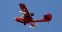
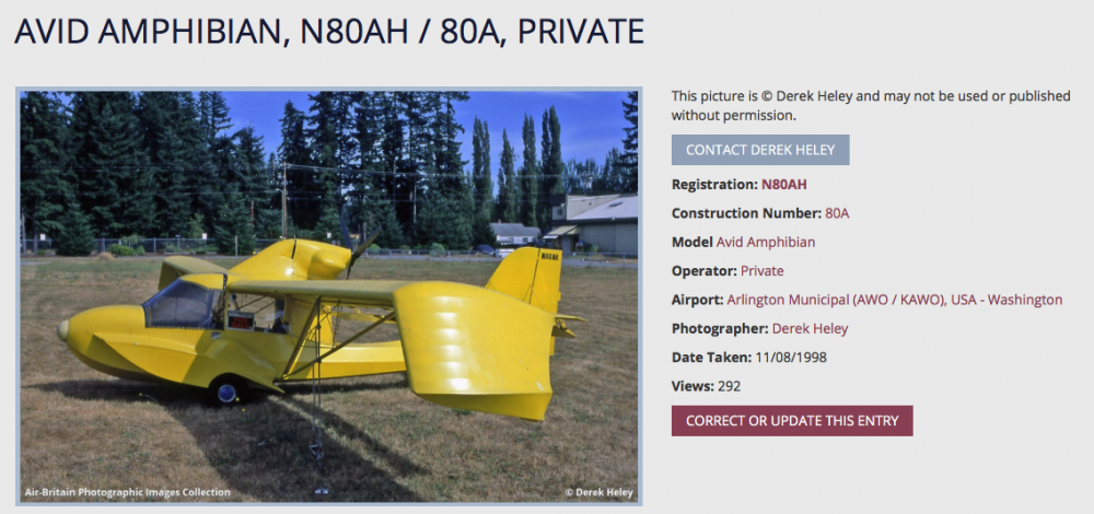
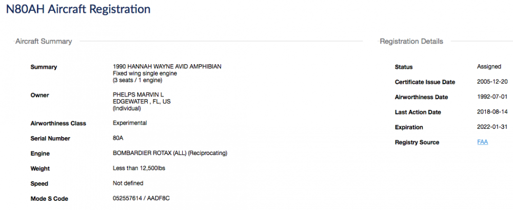
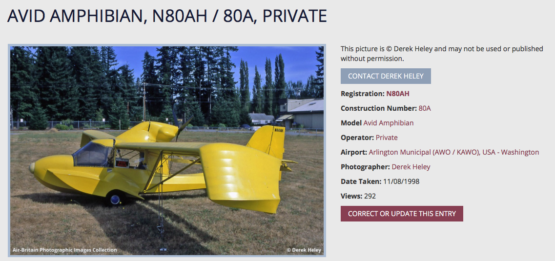
Hey everyone, found this avid amphibian for sale...estate sale ad, probably dirt cheap for the right person. Great project
Here the ad for you : https://afors.com/aircraftView/49225
Found a picture the way it was before..
and some owner info...
-
Hey Allen,
do you know if the black max system is much lighter that the matco system? What is the difference in braking power with matco? Is a double puck brake double the power??There is no information about weight and braking power on the website..
Thanks for your insight
-
Hey Gary,
Welcome , it's nice to have another member out of Canada..I am in the Vancouver area. Nice Kitfox.
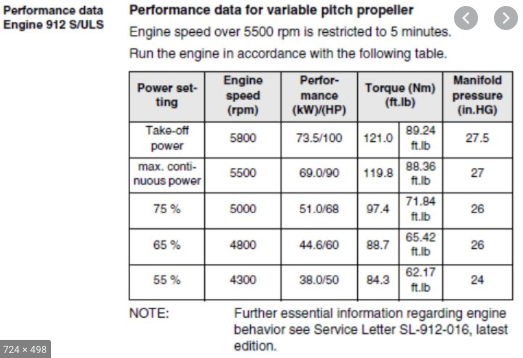
I do have a question for you. I see you are cruising at 5100rpm / 102Mph / 29.0 in manifold and you're using a variable pitch prop. The way I understand this it seems to mee you are operating at too much blade angle for the given RPM giving you a higher manifold pressure which induces stress to the engine according to rotax. At a cruise power setting of 75% it should give you 5000rpm / 26 in manifold (this does not apply to fixed pitch prop...) Please let me know what's your opinion as I am also operating the 912. See the rotax table below.
Am i misunderstanding this table??
Thank you for your valuable input
I am running a IVO Medium fixed pitch prop. Years ago I had a CAP 140 variable pitch that came apart in flight. I left the prop control and MP gauge on the panel as I thought at some point I might be putting the electrics on it to be able to change the pitch. I never did that as the plane performs so well it does not need it. I should have removed the switch from the panel, but never did. I set the prop to get 5800 RPM at takeoff at full throttle. My airspeed reads high by about 5 mph, verified many times via GPS. If I remember correctly I removed the MP T connection...so it is reading ambient pressure...which is why it is at 29". I am redoing the panel and will toss that instrument. I prefer having something vs an open hole for now. Cheers.
Thanks, now that all makes sense
")
-
Hey Allan,
I fly the Catalina with original fibreglass tanks. I use non ethanol fuel and it's working fine. For the fuel level, I have a section of fibreglass from the tank visible (not painted over) in the cabin showing me the fuel level in flight.
These wings give a lot of lift for sure...
-
Hey Gary,
Welcome , it's nice to have another member out of Canada..I am in the Vancouver area. Nice Kitfox.
I do have a question for you. I see you are cruising at 5100rpm / 102Mph / 29.0 in manifold and you're using a variable pitch prop. The way I understand this it seems to mee you are operating at too much blade angle for the given RPM giving you a higher manifold pressure which induces stress to the engine according to rotax. At a cruise power setting of 75% it should give you 5000rpm / 26 in manifold (this does not apply to fixed pitch prop...) Please let me know what's your opinion as I am also operating the 912. See the rotax table below.
Am i misunderstanding this table??
Thank you for your valuable input
-
I just saw some of your pics....that's what I call freedom to fly! really nice. If I'm near Vancouver I will definitely checkout your Catalina!
Can you actually fit two passengers?
The Avid Catalina is not large. If you are a bit underfed/small it's great. To give you an example, My family can all fit .... I am 135Lbs 5ft4, my wife 125Lbs 5ft5 and my son is 85Lbs 4ft9. The rear seat is actually quite spacious as you have nearly 39 in across for one person. In the rear the limitation is mostly leg size and someone over 5ft4 would be too big.
I have taken up a 185Lbs passenger (copilot) and found that to be snug. If both pilot and copilot are in the 180-190Lbs you definitely have to get along....
-
Hey Sam,
I am still in love with my Catalina, no luck here....but if you come close to the west coast we can meet and that way you can fly with my Catalina to give you an idea. Ask any question and I will try my best to help you.
https://1drv.ms/f/s!AvMw5i-09AkLmyLHNPdIaLSnwTWe
https://1drv.ms/f/s!AvMw5i-09AkLtXkUN2SZuTqbxcSM
-
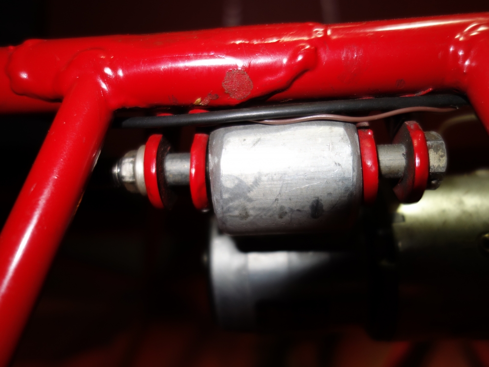
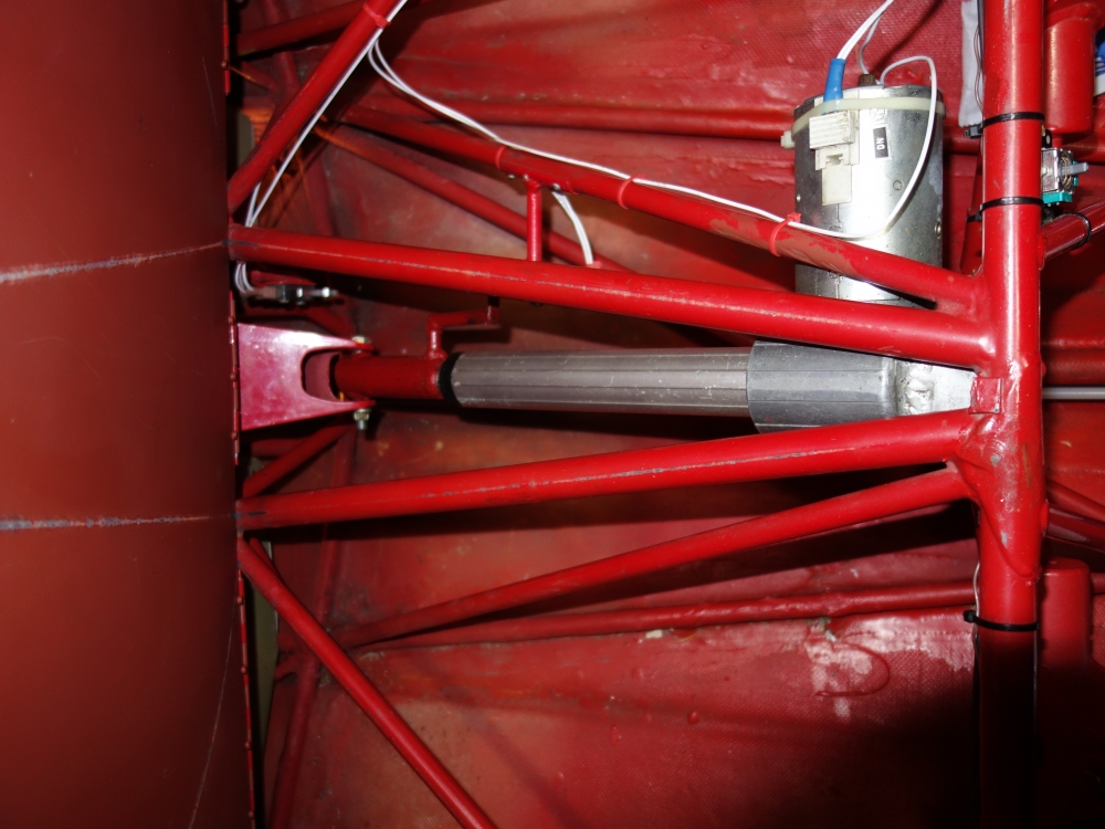
Hey Chris, sorry I tend to forget the price of things....feel better that way. Also this actuator is quite old and i find a bit heavy. I am sure you can find a reasonably priced actuator with similar specs (boats have a wide selection, see trim tab actuator/engine lift actuator/hatch actuator etc....maybe you find a second hand one). The pull-push force to get the gear up/down is not much.....maybe 80-100Lbs. The strength needed from the actuator is mostly when landing at touch down...a bad hard landing will give you a static load of about 3600-4000Lbs. This number is what the actuator has to withstand in compression when retracted (gear down). Any 12v DC linear actuator able to handle 4000Lbs static load and a few hundred Lbs dynamic load will work just fine. You will need about 150mm / 5,9 inch travel. There are some with integral adjustable limit switches...less wiring and simpler installation than mine. If possible I would choose a waterproof one.
-
Hey Chris,
the actuator travel is limited by the two end micro switches, they also switch the lights on the dash. The way I protected the actuator is by a 15A circuit breaker. That breaker will pop if the actuator hits it's end limits (limit micro switch not working) or if the actuator is energized gear down with aircraft on ground. Yes it is a DPDT crosswired switch plus a couple of relays, I'll get you the wiring next...have to do a bit of paper digging
-
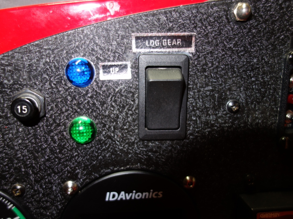
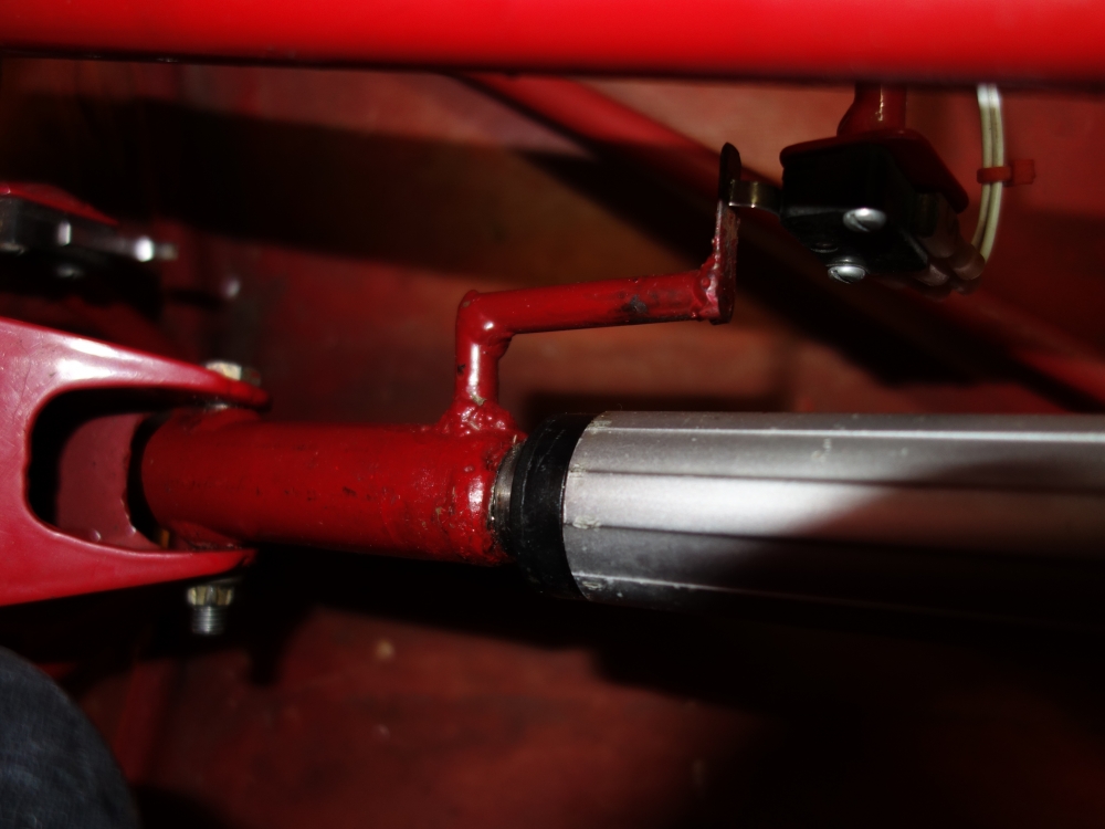
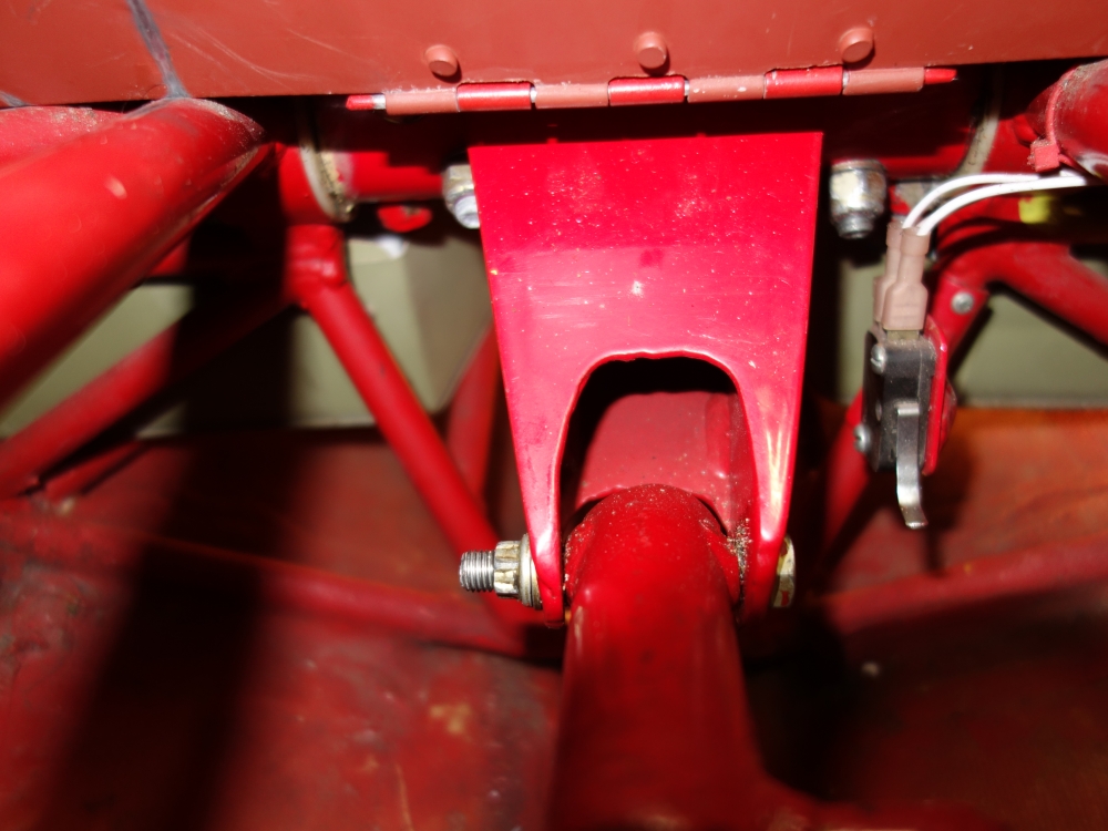
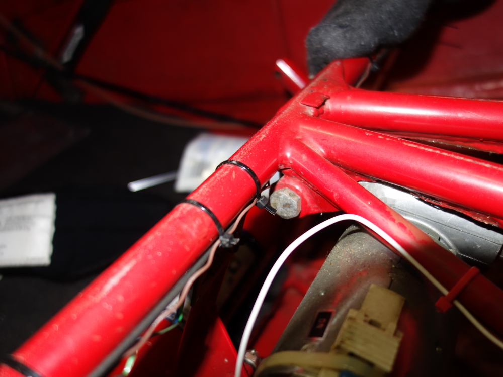
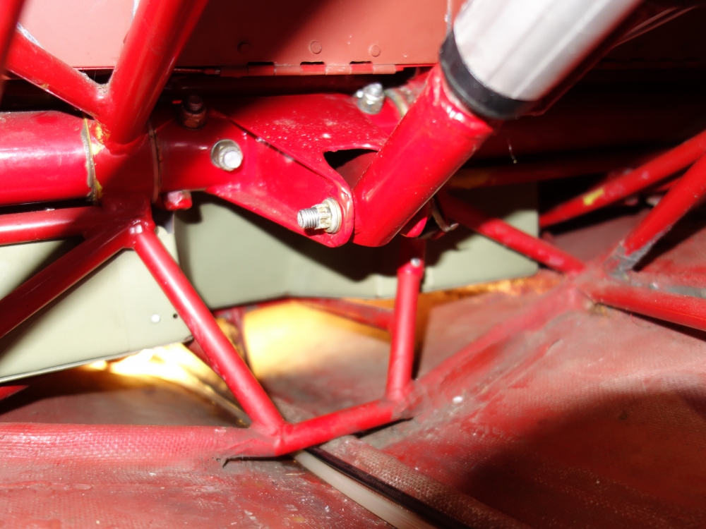
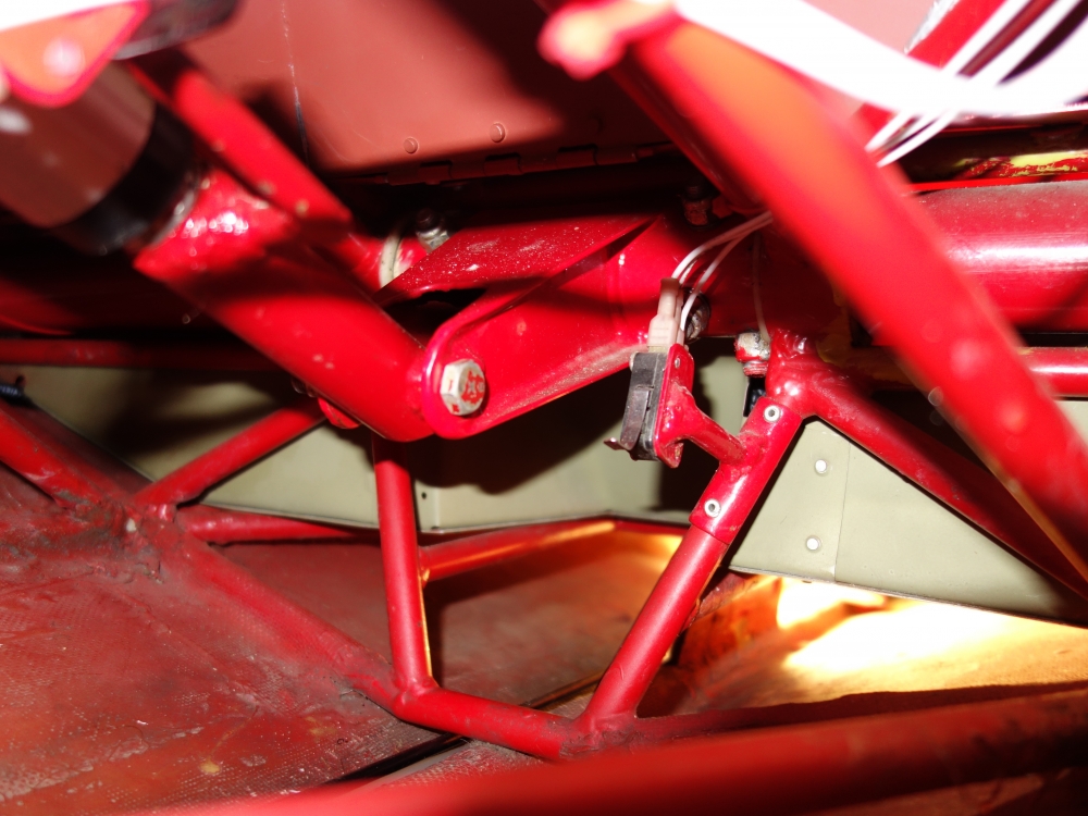
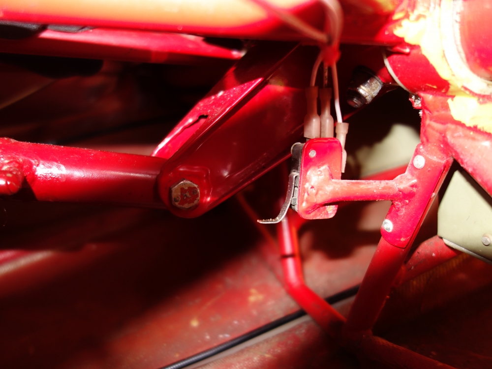
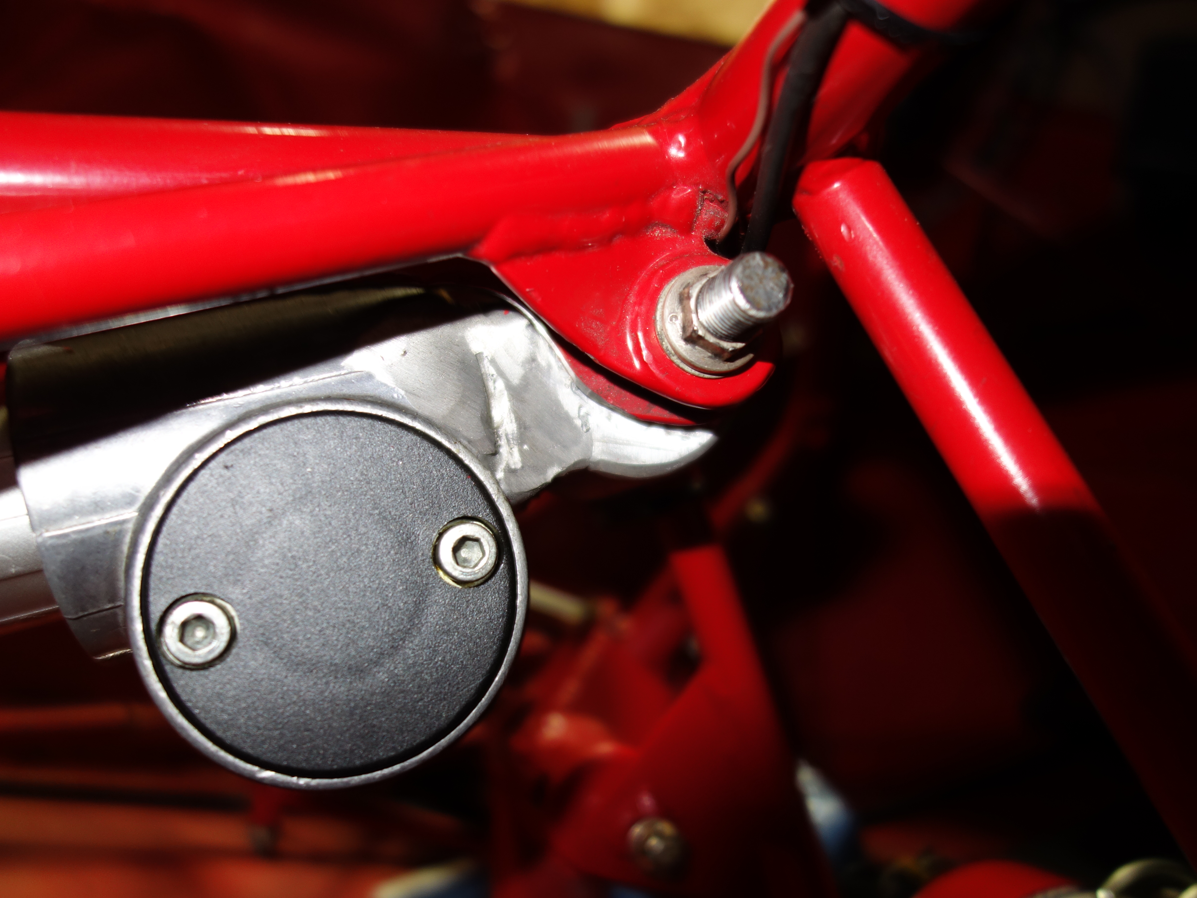
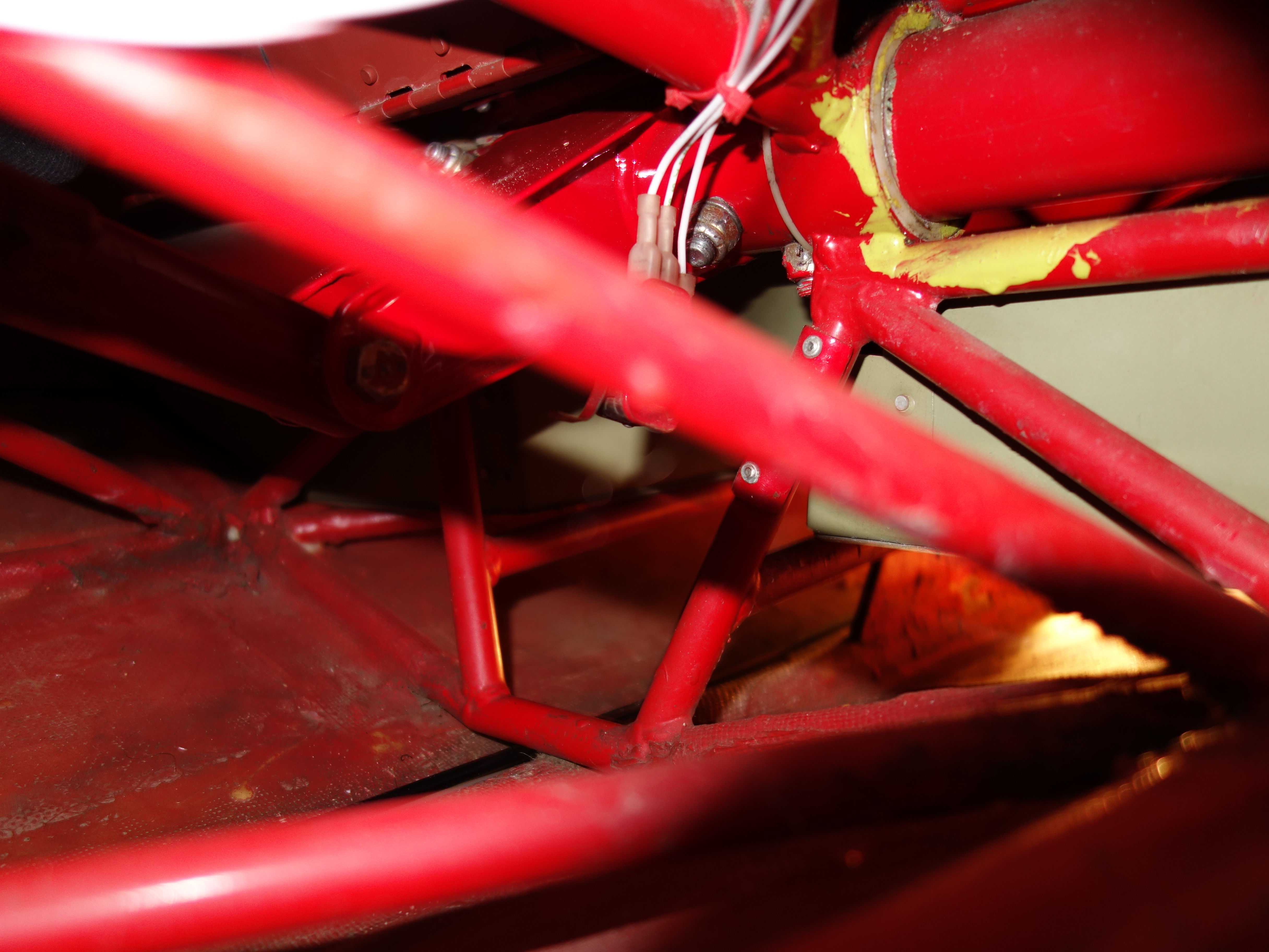
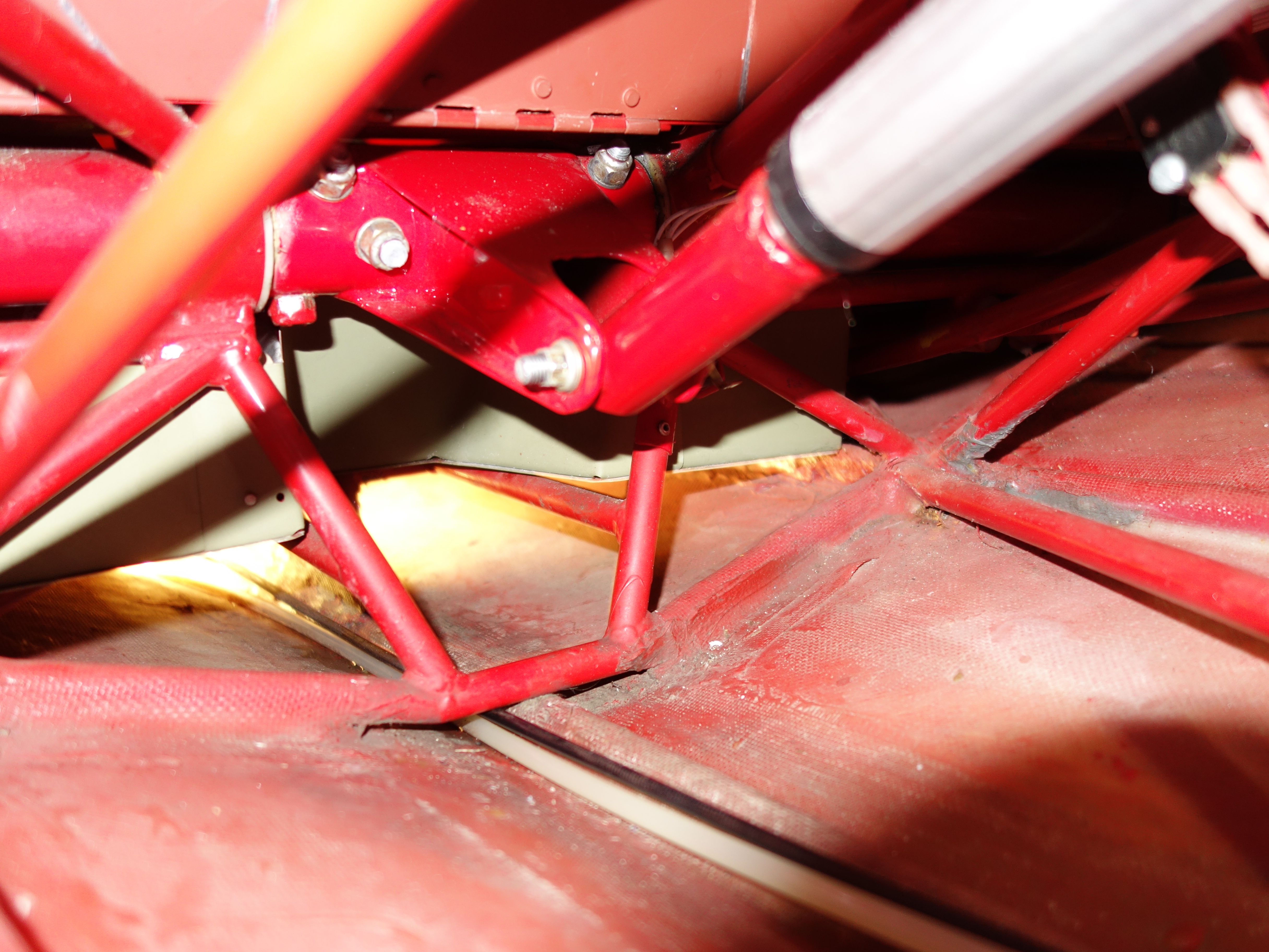
Hey Chris,, here some pictures of the install for you. When photos were taken the gear is in its "gear down" position. Also note the gear switch on the cockpit is a 3 way switch...switch in Gear up =-blue light on, gear up / switch in middle position=no power to system and all lights off / switch in gear down=gear down and green light on.
The switch mid position allows you to not have the bright gear up light on all the time. Also it allows you to partially extend the gear at any position between gear up and gear down.
...my name, Laurent


-
Hey Chris, here a PDF version for you..on page 11 you will find the details. Today I will take some close-ups for you
-
Hey Koffy,
from my experience, you better proceed step by step. Before incriminating the modules (they very rarely brake) go through all your ignition system first. Looking at the pictures I would start over/ take everything off, replace all your ign. wires , check all connectors, grounds , measure the coils , check your trigger coils & gap , measure power cable to the ignition boxes (known to be a problem on old harness) , check your ignition switch circuits (see Jim's advice)
I have spent toooooo many hours trying to troubleshoot the system installed with no success. Only after removing it all making the access easy did I find my issues.
My 2cents


NR Luga prop deliveries
in Avidfoxflyers General Hangar
Posted
Jim, you should have no problem...to give you an idea, I have a 69in scimittar 2 bladed on my 100Hp+ rotax 912 and it works great, no problem absorbing that amount of power
P.s I could not go bigger than 70inch because of the prop hitting the fuselage (catalina pusher)
My previous prop (Warp drive blades) was cavitating and could not handle the power...also 2x weight.