
Tree top pilot
Members-
Content count
137 -
Joined
-
Last visited
Posts posted by Tree top pilot
-
-
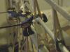
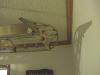
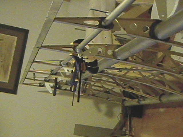
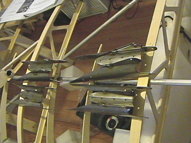
This is how the flaps and aileron attach to the hinges. The aileron has a 1" tube spar/torque tube with ribs as you can see. Offset hinge points with control inputs via closed loop cable. Set up is exactly like the cub except along the rear spar and rear lift strut. Most aspects of the wing are very close to the Highlander design....but I made my wingtips from tubing rather than fiberglass. The flaps are slotted so the hinge point is a bit lower than the aileron. I fabbed these from 1/16" T-6. Hinge points have bronze bushings. I picked up a small toaster oven at the Goodwill and done some powder coating at home....saves time from painting these small parts after beadblasting.

-
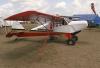
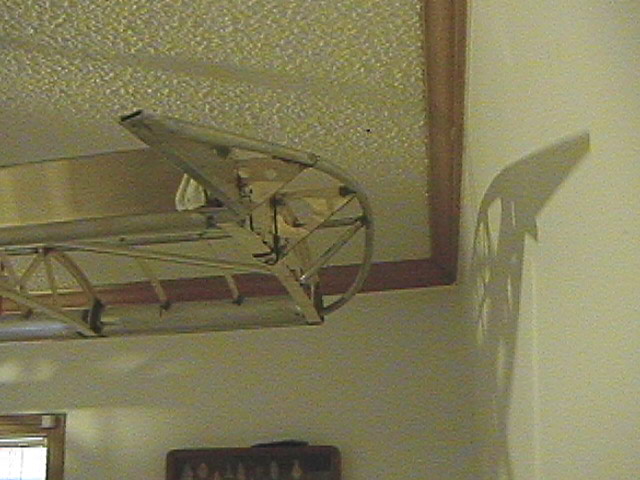
It is this plane here...factory demo..This one was at Oshkosh a few years ago.... say..... around 2001. This plane had the speed wing option....note the rib profile. Built my wings with the undercambered airfoil.....similar to the Skyraider/Avid/Kitfox type of wing construction. Ailerons and flaps are hung from dual hinges attached to the rib's TE .
-
Very cool vid ! I have country similar to that not far from my home field. You guys have to worry about rotors on tha back sides of the larger peaks?
-
Everything I do is a PITA. That is what keeps me interested..all the hard things to be made. My plane is a Ridge Runner. Just trying to keep it as light as possible plus I like working with wood. I just want to cover the leading edges so the fabric will lay out a bit smoother and help to hold the shape. The slotted flaps should work well at low speeds. Almost ready to start covering the wings....not much left to do to the fuse. Engine is ready...all I need to get on the way is a prop. Thanks for looking....pix posted when ready to cover.
-
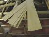
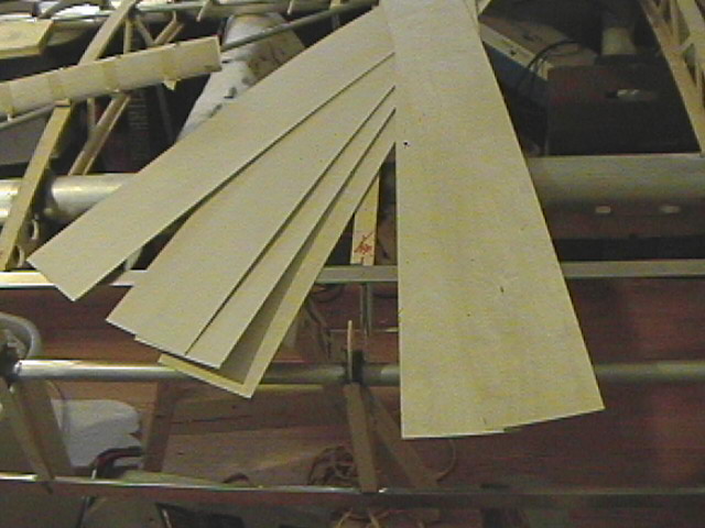
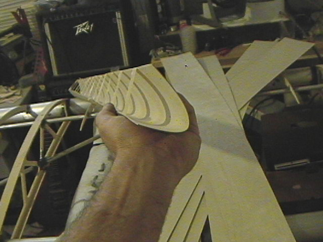
I know that the Highlander used fiberglass....and I was given sawn blocks of 2" home foam insulation board to form the leading edges. I made these from 1/64" ply from Aircraft Spruce with about 30 some pieces of balsa nose ribs to help maintain shape spaced 5" apart. I have invested a lot of time in my mold and process for this....not cheaper or quick to perform.....but man is it light and strong. No steam boxes....just hot water soak and then to my mold overnight. Taped to allow full drying .....praying it won't distort too much. When they are installed and sealed up they shouldn't move anywhere....your thoughts ? Or have I wasted time doing this? If I have to make a mold for fiberglass....I would rather lay them up with Carbon and vacuum bag 'em. Same amount of work either way.

-
Thanks !!! I just couldn't leave the end rib as a finished product. Plus it will get me more effective wingspan. Not a bad bargain at a 1 ld. addition. One more for the going at it...I have made my trim tab on the elevator and have options at this point I think. A good cable or other means of deflecting it? I did weld tabs on it for a cable....but have heard they tend to break quite often. This is planned to be no electrics...with exception of the handheld TX/RX. I would like to be able to trim the stick off and have the backup of it.
-
I am nearing completion of both wings and fuse for the Ridge runner...making ready for the covering chores soon. I think I have asked this question prior to this post , but however I would like to get some opinions before I start adding weight.....unjustly. I know the Just aircraft wing spars as well as the Avid and Kitfox designs employ a length of extrusion to support the spars at the lift strut attach point to spread the load. My spars are 2 1/2" X .065" wall and are 141" long. Lift strut attach point at around 80" from root. Plans do not call for anything of the likes....MTOW will be very near 500 lds. I am not sure if the early single place Skyraider used anything either. Comments welcomed.
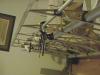
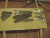
Pic is of my wingtip set-up....very light.
-
For what it's worth....most of all the CG configurations I have calculated are all between 28% and 33% of MAC { Mean Aerodynamic Chord }. This is always used to get a good ballpark of where the CG would be for tapered or straight chord wings. You could make the ribs from aluminum and rivet to the LE of the spar....simple plywood rib mold and cover with .023 sheet? Sounds like a solid idea to move CG foreward.
-
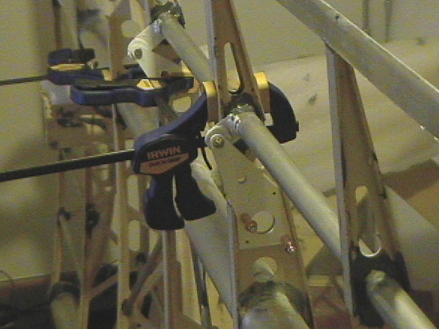
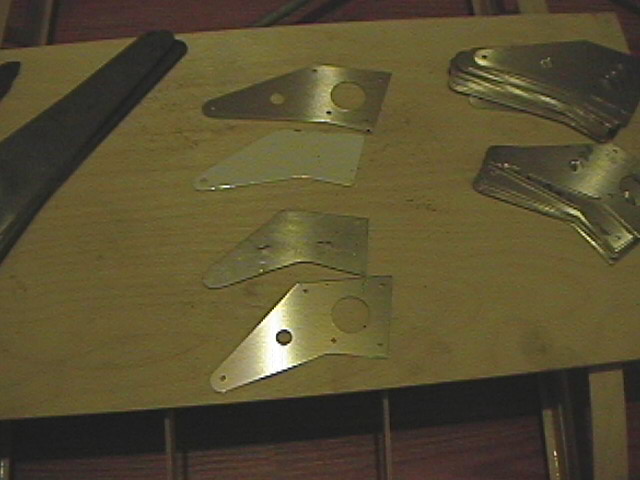
I finally had some time to finish up the spar attach fittings to 95% point. All tacked and ready to finish up. I have made the fixtures to bend the moly plates after it had been drilled and cut to shape. Also a fixture fabricated to align the fasteners correctly- lift strut bolt and pulley stud bolt. These fit like a dream to the tube spar shape. Plus they don't look like an angry shark with one bad tooth made them. This was an fun adventure in creativity for me. I think I am ready to build a fuselage jig soon.....I want to build my own design using this wing design....with a few mods.
-
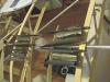
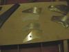
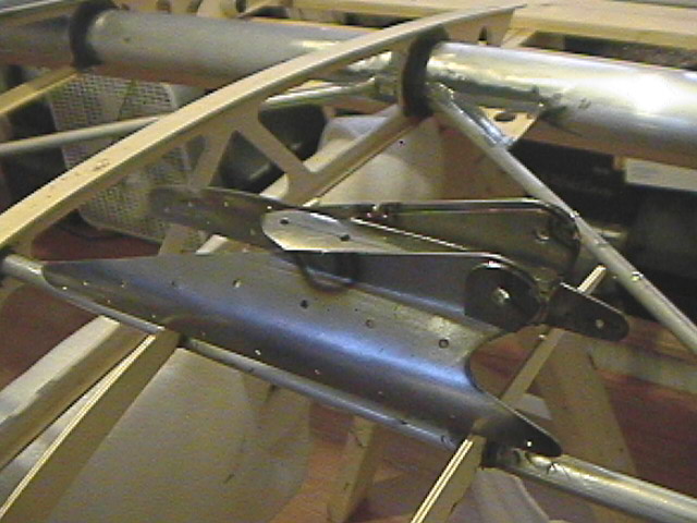
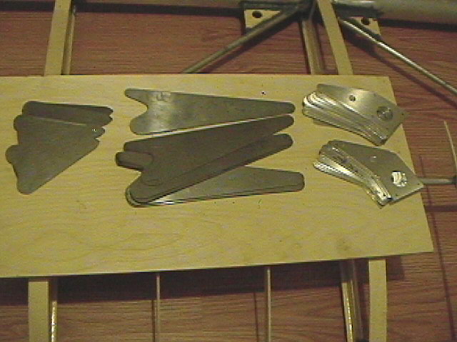
A couple of pics of the aileron / flap hing points that attach to the TE of the ribs. The pieces in the middle is what was supplied to me in the second picture. Also in the parts are the lift strut attach brackets before drilling, bending, and welding. I have made a jig today to bend the lift strut pieces and to position the aileron cable bearing bolt for welding. Stay tuned....pix when welds are complete. Have to fab up tie down loops and wing hold-together brackets for when they are folded.
-
One caveat with the Stewarts system.....they use isocyanates to set up the materials. This will absorb through any exposed skin...even your eyes. Bad stuff....
-
Too cool.... I can't wait to fly this year......maybe.
-
OK Thanks for the reply. I am always trying to think ahead and have a structure that will last a while. A friend said that a good airframe is worth two or three low time engines....
-
My manual states to sand away any coatings on the wing spar doublers before attaching with Hysol adhesive. Question is that the aluminum is going to begin a corrosion process or is the epoxy going to have enough film tension to create a barrier when riveted ? Just wondering about this.
-
Seems a -4 Cherrymax would help to stregthen the spar attach and doubler fittings. I can't locate a strength table on the stainless pop rivets supplied. Anyone use the max rivets instead ? Just looking to make a bit safer/stronger. I will try and get a scale for a pull test and see what it takes to shear the supplied fasteners this week.
-
Anyone considered these as opposed to the SS pop rivets ? Seems a -4 {.125"} would work just fine on the strut attach fitting and the root doublers. I have been unable to find any stregth tables on the SS rivets supplied to me. Just wondering again....trying to improve and make a bit safer.
-
So what to do now? Re- work the wings and bend the carry-through tube? Leave it as is and make bigger supports for the wing tube? Wished I had not baught into their kit now...as I have had to replace most everything. Now this. Shame on these guys for not getting this a bit closer! Shame on me for not catching it before drilling.
 I can't simply cut the tubes off and restart because the spar attach fittings will be into the ribs...and I am not re-making the lift struts. And not looking to shorten the brackets. Looks like I kicked myself square in the teeth. You guys have had a look at the Kitfox I mentioned earlier? Looks like the same deal. Just stuck now with this seemingly endless issue. Spar hole center to center is 27.25".....a bit short.
 -
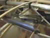
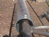
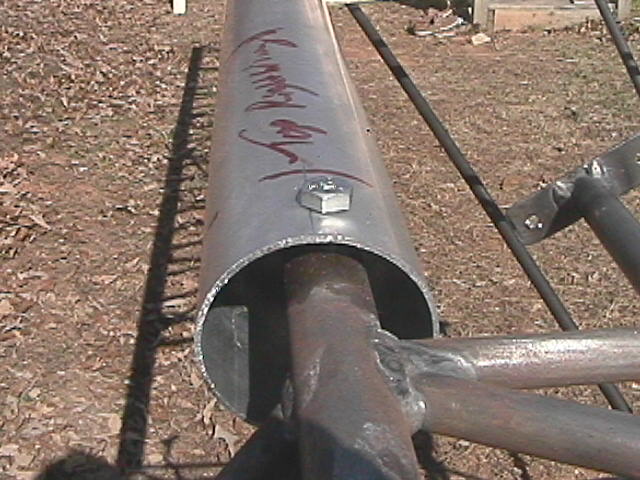
This is a shot of a drill through the tube. The other wing is a bit worse as far as the offset to the rear of the tube. The edge of the hole on the other wing is almost 1/8" behind the centerline mark ! The only way to remedy this is to rework the carry through tube on the fuse I guess...or leave it as is. I am just pissed that there was not a better fit...and better parts than I was supplied. I would lose a small amount of span.....and a crap load of work to re-do to make this correct to me. I know these are not type certified aircraft, but please make an attempt to fit things though design before you send it out. Then again it was my fault for not checking this before hand. I could have shortened the ribs to get this right. The guy that has an online Kitfox build log...http://tropicaltuba.com/Kitfox%20Project/images/387.jpg This shot appears to have the support plates well behind the tube center line. I am uncertain as what to do with my situation. My instructions were to drill the rear spar tube top hole first. Then the wings would be mounted and the front holes drilled after setting them in correct relation to the fuse centerline. This has been a nightmare so far. Oh the joy.
-
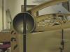
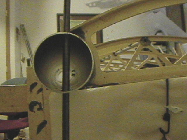
Assembled the wings to the fuse and all the wing building chores can be finished now. The thing is that the carry through tube in the front do not center up inside the spar tubes. It appears that they are about 5/16 OC off of the centerline of the spar tube. Is this a common thing? I would tend to think that the rear spar has more lift load than the front...may not be critical. I just wondered if any others have noticed this on their plane....normal or not. You can see in the pic that I did mark the center of the spar tube...and the ending results.
-
It is a Ridge runner...very similar wing design to a lot of these smaller fun machines.
-
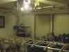
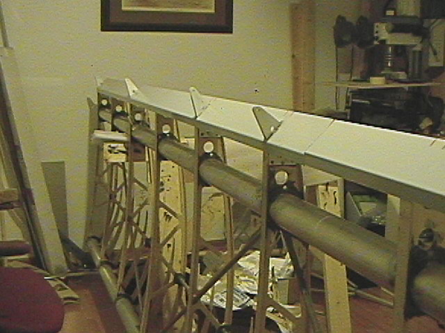
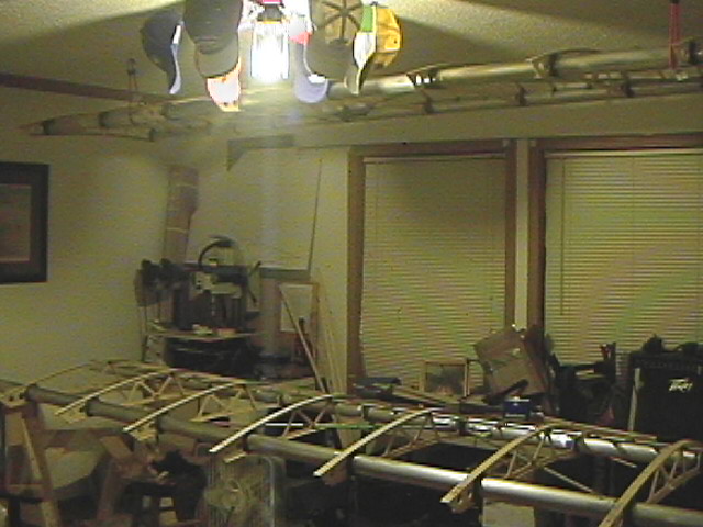
I have managed to get the wings built and ready to set to the fuse. Went by a friend's machine shop and picked up a new set of reamers to clear out the weld burn-throughs on the lift struts and create the spar to fuse holes. I have replaced everything but the ribs. The other parts were simply un-usable. Should be able to move along a bit now. Hoping to fly it this year. I am going to really try and put in more than 20 hrs/week to it now. I know...pix or it didn’t happen. Beware the clutter of my corner of the building. Most of my time has been remaking parts...all I have left to remake is the spar attach fittings and I think the fab work will be mostly over. I have built more than 75% of what I have at this point.
-
Found this this morning....may be a good deal? Wish I were closer to look it over...but would probably buy it and get C box on that engine.
AVID FLYER • $6,000 • ACCEPTING OFFERS • avid flyer complete kit 532 rotax 2.58 gear box 6,000 or best offer got to go jim graen 763 856 2527 • Contact James G. Graen, Owner - located Zimmerman, MN USA • Telephone: 763 856 2527 • Posted February 3, 2012 • Show all Ads posted by this Advertiser • Recommend This Ad to a Friend • Email Advertiser • Save to Watchlist • Report This Ad • View Larger Pictures • Finance New Lower Rates!
Registered Copyright © 1995-2012 barnstormers.com All Rights Reserved.
Legal Notices
-
Copied from the interweb from an aerospace company deposition of structural docs sent to me from a friend in the industry....
Basic principles for long-lasting bonds in critical structures involving composites and aluminum.
The basic principles for long-lasting bonds are well filleted joints and resistant oxides. A large number of pretreatment processes have been developed for aluminium.
Some of the most common (and some of the more unusual) are presented here. Choice is determined by the environment where the aluminium is to be used, likely stresses and costs.
Full details of the processes and any risks to the work environment should, of course, be obtained before starting any form of treatment.
The main purpose of priming prior to the bonding of aluminium is to fill (seal) the surface when high-viscosity and/or fast setting adhesives are to be used.
Priming becomes more important where the aluminium is to be used in a corrosive environment and no surface treatment that improves corrosion resistance (e.g. anodising) is contemplated. Primer also “impregnates†and strengthens porous oxides, e.g. after chromating.
Requirement specification
It is advisable to draw up a requirement specification for the properties of the final bond and the use-related aspects of the adhesive. This helps crystallise the demands really being placed on the adhesive. It also makes it easier to specify exactly what is required to the adhesive manufacturer.
Pretreatment operations in bonding
Process
Result
Use (max.)
Cleanung/ degreasing
Minimum requiement for ensuring a clean and defi ned bonding surface.
For moderately stressd joints in dry surroundings.
Fine grinding/blast cleaning
Removes weak surface layers e/g/ oxides. Safer than degreasing.
Highly stressed joints in dry environments. Unstressed joints in fresh water.
Boiling water for 5 - 10 min. after pickling
Gives resistant, but moderately
strong oxides.
Lightly stressed joints using
flexible adhesives in humid,
corrosive environments.
Phosphating/
chromating
Corrosion resistant, but weak,
porous oxides.
Lightly stressed joints using elastic
or very low-viscosity adhesives in
corrosive environments.
Hydrochloric acid
at 20°C for
30 seconds
Quick, can impart a dark-colouring
to the aluminium surface.
Moderately stressed joints, even
in corrosive surroundings. Relatively
uncommon process.
Etching in
chrome/
sulphuric acid
Thin, strong oxides. Long used
in the American aero-industry.
Highly stressed joints outdoors.
However, cannot withstand strongly
corrosive environments.
Anodising in
sulphuric acid
Thick very resistant oxide.
Lightly stressed joints in corrosive
environments. Best with elastic
adhesives.
Anodising in
chromic acid
chromic acid Medium-thick, strong oxide.
Used in the European aero-industry
since the 40’s.
Highly stressed joints, even in
corrosive environments
Anodising in
phosphoric acid
Porous, very resistant oxide. Is used
together with low-viscosity primer.
Optimum pretreatment for highly
stressed joints in corrosive
environments.
Hope this helps and not offending to anyone...I will be using phosphoric acid method...Like to know all I can about the methods and reasons why......
-
The manual I have states to use PPG 533 cleaning agent that is phosphoric acid based...no mention of water dilution prior to use or rinsing it off. Another option is to use Dow 1205 that is made up from Toluene, Methyl ethyl ketone, and Dipropylene glycol monomethyl ether-a plasticizing agent. I have also read that the Highlander manual states that acetone or MEK as being good to use before the 2 previously mentioned products. These will only have a degreasing action. Is it going to be a problem not removing the oxide layer or keeping it off before bonding the ribs using acetone or MEK?
I did see someone mention that without alodine , you would only get 30%-40% bond strength. So what gives here? Lost in the debates of what to do....and not getting anything built in the process. What did you guys use or do? Abrading the surface with aluminum oxide based products like red scotch bite and emory cloth from 3M seems to be counter productive in getting rid of the oxide layer to be bonded....or is the acid supposed to remedy this problem?
Thanks in advance..sorry to be a PITB...I just want to do this right - the first round

Aileron / flap leading edge
in Avidfoxflyers General Hangar
Posted
Yes folding wings are standard all models. The TE is aluminum.....same that Aircraft Spruce sells. Plan on using light cloth with polyfiber system....I am allergic to isocyanates...hardeners. It is made from cyanide you know and if you use it you better cover yourself up totally and have a fresh air system. That stuff will penetrate you eyes...any exposed skin. Really sour on them for not telling customers the whole truth about the hazzards of the product line. Sorry for the rant....