wypaul
Contributing Member-
Content count
942 -
Joined
-
Last visited
Posts posted by wypaul
-
-
Randy what are your "arms" for your airplane? Mains, TW, header, baggage also your weight and pass weight. I ran your weights with my arms and it appears that you will be fine without the added weight but the big caveat : follow the instructions in the manual measuring and weighing everything for yourself and then do your own WB. If you purchased this plane with a WB do it again yourself. Well that is what I would do.
Also the arms behind the datum will be positive and those ahead of the datum will be negative.
-
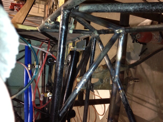
Another weak point that needs a triangle is horizontal on the lower longeron and just ahead of the seat truss under the floor boards. My MK IV has a triangle formed by tubes at that point that I filled with plywood after repairing the structure there.

-
Ed, not sure how to get the photo from the photo section on Yahoo.
]http://groups.yahoo.com/neo/groups/avid_flyer/photos/albums
This one works for me, hope it does the job for you Ed.
-
Herman I don't know if you noticed this on the Yahoo site but it looked interesting as an alternative to the cables.
This is message 36437 on the Yahoo site
Those comments on the wire as too hard a stop, the proposal of an additional bungee-cord loop with a stronger cord, that all is quite interesting An idea I am elaborating is to make an additional bungee loop but one that ties horizontally both landing legs just below the cockpit floor. The good thing about that is that with usual, not to big inflexions of the landing gear, that bungee loop nearly does not get extended atall, this, is, it makes almost no additional force even if that bungee cord is very strong. Only when the deflection is quite important the bungee starts to work but very progressively, linearly. I have written down the equations that describe the force delivered by this proposed bungee of mine and I am analyzing the way it works a bit closer and hope to be able to give a quantitaive description in two or three days. This notice today is just to hear if someone has implemented such an idea before and if yes, to hear what his
experiences have been with it.
Cheers JuanSomething to consider perhaps. I am using the HighWing Bush Gear and am happy with that after a little work to the truss and fuselage sides to beef them up.
Here is a better explanation in message 36444:
In that question of protecting the fuselage of he Avid against damage at hard landings there has been made the proposal of replacing the security wire loop and also the proposal of substituting it by a loose loop of a much stronger bungee cord. This proposal makes at first sense but I fear that in reality it will be very difficult to find and install bungee material suitable for the task.
My proposal is a different one: remove that wire loops and add to the landing gear an additional "suspension mechanism" in this way: install loops of bungee cord placed horizontally below the cockpit floor, each loop passing through the space delimited by the horizontal tube of each landing leg and the stiffener running down, this is tying both landing legs together.
I have written down the equations describing the behavior of such a suspension. The results are described with the attached graphs. In those graphs the X coordinates is the deflection of the landing gear given in degrees. The Y ordinate is the vertical force ("weight") on the landing gear originating this amount of deflection. The redline is the relationship between force and deflection with the standard Avid landing gear installation. The black line is the additional effect of my proposed mechanism. The blue line gives the result of combining the two suspension loops.
There are two graphs the photos of them I have posted to the Group in a file "Ne Suspension mechanism". The one where the lines run more horizontal, this is, where the suspension is softer, corresponds to adding "my" loops having the same elastic values as the standard bungee cord loops. The other graph corresponds to adding "my" bungee loops with stiffness 3 times higher than that of the standard bungee cord.
The interesting thing is that "my loops" do not appreciably contribute to the suspension below 15° deflection. Beyond that point they progressively contribute to stiffening the suspension. A very positive point, I think, is that the elastic properties of "my loops" can easily be adapted by just adding loops as needed or considered convenient. Last not least is is a very positive point that the force created by "my loops" is a compression force on the stiffener of the cockpit floor. This means the bending forces on the stiffener remain as before, the new mechanism charges on the same stiffener but with forces running otherwise. In total the stiffener is charged in a more convenient way, less prone to damage it. -
The Avid was not a 51% approved kit either, and there is a checklist that you will probably be required to fill out and score to ascertain that the plane qualifies for 51%. On both of the planes that I have built neither the FAA guy that inspected my Q-2 nor the DAR that did the Avid even glanced at the builders log or pictures. That said who knows what the next inspector will want to see. So you are right in keeping a "builders Log" to cover your bases.In my case, since I did not buy a "51% approved Kit", and mine is "scratch-built", the log and photos are absolutely necessary, IMO, to prove that I actually built more than 51% - mine is closer to 99.44% pure homebuilt, just like Ivory soap.
That is, if the inspector knows what he is supposed to do - but so many of them dont!
EDMO
-
Well owning an airplane and flying is great but being debt free is even better! Don't know if you are into Dave Ramsey but his stuff is right on.
-
Ed he is talking ELT not xponder, no xponder required except for class B and C and even in C you can get permission to enter if you request it.
-
Thanks guys I will have to consider that option.
-
I have an Avid MKIV with the standard cabin heat setup that takes air from behind the radiator using the supplied scoop. This is not working, anyone have a muff style heat setup that is working. I have been thinking about adding an opening in the cowl so that the muff gets ram air to supply the muff. Any thoughts. The engine is a 912.
-
The IV fox fuselage must be a foot longer than the Avid MK IV.
Does the Fox call for a vent for the header tanks?
-
Just plugging in the weights that you provided in your W/B with the Arms for my Avid I get an empty CG range of 12.89 and it seems strange to me with nothing heavy to the rear that you are having aft CG problems. Will you please provide the arms for your aircraft. Did you measure the Arms yourself? Weights are without fuel I assume.
-
I can read mine better in the sun. The red lamp is nice. I glance at the graphic but for sure the numerical is what I rely upon. I do not use the Rotax mode and ordered the different senders for the CHT so the unit would display more readings. I also installed a water temperature gauge (analog) which is not necessary with the Evans waterless coolant that I am running and may remove it someday.
I have mine setup to read 2 EGT's, 2 ,CHTs, OT and OP with the Voltage and the RPM.
-
I bought the E3 which is a smaller 2 1/4" unit which I like but I do wish that I had bought the E1. The E3 is hard for me to read due not only to size but lighting also.
-
Interesting, thanks for the heads up Paul.
-
Ed may I suggest that you look at Tygon for your hosing pleasure.
 It is available in the size you are looking for.
 -
Ordered a new pump for my 912A, with 65 hrs on it probably not necessary but they run better with fuel.
-
Attended a great little fly in at 76V today. Free breakfast, free lunch, prizes and can you believe it $50.00 bucks gas money for every pilot that showed up with a plane. Hope they don't find out that we would pay $50.00 to come down to the grass strip fly in like this. Flour bombing and balloon popping contest and a toy drop for the kids.
Glendo is a tiny town of a few hundred people and owns the airport.
13 planes, a powered paraglider and one hot air balloon showed up. Don't you know I will be going back next year. Oh yes, and about 5 nice RC planes. About 200 people just came to enjoy the day.
Anybody close should put this one on their calendar for next year.
-
I suggest using a CarbMate or the likes to get the carbs balanced pneumatically. My 912 was not close by doing the mechanical balance job and would not run smooth at higher RPM.
The other Paul S.
1 person likes this -
I had one of those dial gauges in my KF3 wing tank. Never leaked. Easy to see fuel level with a very quick glance. Wish I had them in my KF4 tanks, much harder to see fuel level with sight gauge IMHO. Thinking of installing the Belite LED gauge this winter, saw them at OSH and Kitplane Mag just did a little write up.
The Belite gauge looks good. What sort of sender are you thinking about and I assume that it would be in the end of the wing and tank.
-
These Rochester fuel gauges work great and aren't too costly.
Can you tell us a little about how they are installed. Were nutplates installed to screw the gauge into?
-
I did clean off a section on the end of the left wing last time I had them off but did not remove the fabric from the butt rib so it was visible. Need to get around to completing that. Maybe manana. Thanks for the reminder. Oh, I did buy the rudder pedals from Michael but haven't installed them yet. Very nicely built.
-
Good point ED, thanks.
-
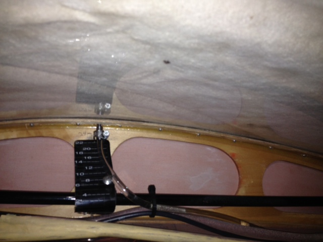
Paul, I see a chart there - does this vent line accurately show the amount of gas in your tank too? On the ground, or in flight too?
EDMO
On the tailwheel it shows about four gallons of fuel less than what is contained in both tanks. As I mentioned in the earlier post it now reads what is in the tanks at 5000 RPM while in flight.
Afterthought to my ramblings above - You could use epoxy or 9460 to bond aluminum female fittings to the side of the tank and not worry about having to drill and tap the holes - a very small hole behind the fitting into the tank would be enough for a vent or sight gage.
EDMO
If I had it to do over I would probably go that route Ed and may sometime in the future but at the moment I am not in any hurry to contaminate the tank by drilling into it. Maybe this winter I will build an air powered vacuum and tackle that project.
-
I made it out to the hanger and took a couple of pictures of the Vent/Gauge setup that I am using. This is plumbed to the top of the header.


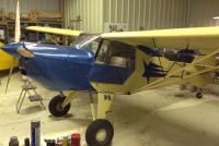
$240,000 Super Cub???!!
in Avidfoxflyers General Hangar
Posted
I bet with That 409 out front there isn't much stol left in it. Think I will stick with my little Avid.