saskavid
Contributing Member-
Content count
192 -
Joined
-
Last visited
Posts posted by saskavid
-
-
Well from an appearance standpoint what you have there should enable you to flip that airplane on its back from whatever ground speed you choose to stand on the brakes at.... You have mentioned brake line rigidity.... I am running a clear line called parker parflex 1/4 inch line on my plane rated for only 450 psi or so working pressure and can get all the pressure I need with it. I have used this brake line on a test stand setup just to see what my brake pedal design would do and it gets to 600 psi. Others are running a 1/8 inch line matco sells as well. doesn't seem to make any difference it all works.
I've never worked with a kitfox but just eyeballing it I would say static leverage is 3.6 to 1. and the way it is setup there should be minimal degradation with activation.
-
sorry for the late reply... I cant hold the plane with the brakes above about 3000 rpm even with dual calipers on each wheel . I installed a pressure guage on the wheel cylinder and I am only seeing 220psi if I stand on the brake pedal really hard.... I talked to matco engineering and he said the brake pedal geometry is wrong, however looking at my brake pedals, they are stock kitfox IV pedals and I dont see how to get any more mechanical advantage.....A small master cylinder might make more pressure....Im stummped for now....
I removed my 503 rotax and am trying to install a blue head 582 new engine... I have a different mount coming that has two vertical rails on each side and 4 small aluminum brakets that bolt on the corners of the engine...even that Im running into problems.. I have 3 of the mounts on but the left front side of the engine has one 8mmx1.5mm bolt and one hole is smaller and off center . I know I have to drill and tap and new hole and I am guessing with the mount so it is horizontal and vertical with teh engine....the new hole would be right next to the smaller hole but if I use that the mount bracket will be crooked.....
Well if this is all you are getting for pressure and holding sounds like air or maybe the caliper is binding on the guides, or both. does the plane have the E style parrelogram brakes or the earlier ones? A lot of guys are filling their brakes from the bottom up thru the bleed screw using a piece of tight fitting rubber hose and a veteranarian srynge to make sure all the air gets out.
-
So can you hold full power on a runnup or will the plane creep away?do they feel spongy beyond typical flexing in the rudder bars and pedals themselves? If you have air trapped somewhere they won't work for nothing no matter what you do. And it can be dam tough to get rid of it sometimes.
Do you have vg's on the tail as well? Horizontal stabilizer underside just in front of the hinge point?
-
What I remember from flight training was 60deg angle of bank expect the stall speed to increase 40 percent over what it was straight forward stall. At 75 deg. it was 100 percent increase in stall speed. 45 deg. is 18%
-
Ya know just to see if it could maybe be done I went to work and designed a mixer for my avid that should produce like 2.7 to 1 differential and still allow the wings to fold without disconnecting the controls.... Everything works.... on paper. Just a matter of getting ambition up and building the components and seeing it if actually works on a physical plane. And that is the reality. Don't have the time and ambition to tackle it. Would take a lot of time or money or both probably. Just not in the mindset to do it. Then there is also the question of how much up travel on the alerion is structurally acceptable. My plane fly's without it. for now.
1 person likes this -
Well the trick is to get the activation shaft of the master cylinder as close to the back of the rudder pedal as you can to get max leverage potential. You have a bit of room there to work with. You can tip or cant the tops of the brake pedals a bit further towards the pilot if you are comfortable with how that works for you physically or you can cut the tabs mounting tabs off the brake pedals and weld new ones on where they need to be, put the tops of the brake pedals where you personally like them to make everything work to your personal preference and get the most leverage you can. One thing to try and avoid in any mod is getting a condition known as an over center where the master cylinder actually starts to rotate back towards the redder pedal as opposed to away, where the system then has potential to act like a vise grip and lock itself up.
-
Don't ebay that much. Just how often do they actually put on promotions like this?
-
Downside to the 8" Douglass wheels are the absolutely sub par Matco brakes that go with them.
The only way to make them work acceptably would be to add a second caliper on each wheel.
I happen to have two sets of the calipers also. Is it possible to add the second set on too? I know I have seen double set ups before?
http://www.avidfoxflyers.com/index.php?/topic/530-go-kart-to-matco-brakes/&page=1
Hey Vance: I would suggest you read this thread to assist you in understanding what can be done and what to expect regarding the brakes you have and how they can be made to work within the limits/understandings of the physics that have been achieved.
1 person likes this -
I'll add this... I run my matco tail wheel with compression springs as I think most people are doing. and like the above video run them loose enough to keep any binding from interfering with the unlocking mechanism. I am also running with a light tension spring in the mix. running it inside the compression spring to keep the unlocking mechanism under a constant spring tension that will ensure the wheel stays locked until I want it unlocked. This is not something matco specifies but after reading in their literature that the mechanism is designed to release with light spring tension.... as well as addressing the reality that without constant spring tension it can come unlocked.... the obvious answer is to do the dual spring setup to accommodate the mechanism...On my last tail spring setup I got the compression springs for steering the tail wheel too tight and it won't release without some added horsing
-
Depending on how fussy you are about the appearance of the welds inside you could get a piece of non conductive carbon rod to fit perfectly inside of the pipe shell you are welding on and control exposure to oxygen and give any melt thru essentially no place to go. Coming up with a place to get a piece of carbon rod to fit exactly inside and completely compliment the radius will be a perhaps bigger challenge than it is worth.
-
I concur with Joey"s sentiment.. Don't fly this plane until you get a full understanding of what is creating this anomaly and rectify it. I would suspect some sort of in congruent deployment of the flaps when the flaps are in full position deployment. What is causing it if it is the problem I couldn't tell you.... At a keyboard it is just all speculation.
1 person likes this -
So how much down elevator travel do you have? The manual indicated limit I am taking from memory is 17 degrees. Where are you at?
-
I used clear graphics vinyl, cut and spliced to suite. Been there for over 12 years now. Joeys thread will cover how it attaches and where exactly to put it.
-
If it has what is described as a round kitfox type cowl, what you are probably looking at is that aftermarket cowl that Lee Dubay developed for the avids. Avid did offer it with their kits as an option for a while. Called it the Avid Avenger package.
-
One thing you could try is to get an after market windshield washer setup and install it into your plane and use it to spray water on the rads as required to control heating. i do have on installed on my model c with internal rad and use it from time to time on hot days in climb out.
1 person likes this -
In terms of desquirrelifying my own avid, I did these things.
On my matco tail wheel I run compresson springs a bit loose with weight on the tail as well as then having a light thin tension spring run up the center of the compression spring to keep the steering arms under constant tension so the tail wheel can't come unlocked inadvertently.
Pivot bolt geometry of the tail wheel can/will have an impact on the handling of the aircraft on landing and deceleration. Positive caster steers easier but is typically more squirrely than neutral or negative caster. Ran positive caster for a long time on my plane and because of it learned to land/ taxi using brakes only for directional control. For me the best rule of thumb became to use the brakes to steer the plane in a straight line, use the steerable tail wheel only when you need to turn the aircraft.
The most important thing I did was rework the toe brakes on my plane so I could be confident I had full effective control in taxi and landing. Joey's thread Gocart to matco brakes covers that change up.
1 person likes this -
Boy that really hurts to hear..Sure glad you are ok but still hurts to hear about it every time won of these heart and soul projects of someones gets banged up..
-
I want to ask if I understand the MC bore comparisons right: The smaller 1/2" bore would take more pedal travel to disperse the same volume of fluid than the larger 5/8" bore, but possibly you could make more pressure with the smaller one? EDMO
Yup that is the working theory. It is the leverage determined by the ratio between the surface area of the 2 pistons in the system.
1 person likes this -
Good to see you are still around Mike. I installed the intensifier kit to the MCs when I went to the 27s. I locked em up on dirt the other day.
Hey Joey. Ya still kickin. Interesting to hear about the intensifier experiment with your plane and how it worked out. With the avid rudder bar brake pedal design a smaller piston in the mc should lead to more pedal travel and less mechanical leverage. But I think the crude math i did a long time ago showed the intensifier would help like 10 percent with the avid setup on paper with the single w62 caliper on the hydraulics improvement end of things squared off against the mechanical loss.
Sooo - I have Grove Brakes, and the one set of Grove MCs I have are 9/16" bore - To add another set of MCs, or to change to 2 sets of Matcos, would it be better to use the Matcos with 1/2" bore or 5/8" bore? I have both sizes. Or possibly, a set or two sets of some kind that I removed from a Piper with Cleveland wheels & brakes? EDMO
Well I suppose there is a formula for determining optimum ratio for piston sizes in a hydraulic brake setup but I don't know what that is. Multiple caliper or caliper piston setups would preclude the use of larger mc pistons so as to mitigate excessive piston travel to get fluid activating the caliper pistons. Final success is about building a leverage structure that can successfully turn leverage into line psi...not only on paper but on the plane itself.
-
Good to see you are still around Mike. I installed the intensifier kit to the MCs when I went to the 27s. I locked em up on dirt the other day.
Hey Joey. Ya still kickin. Interesting to hear about the intensifier experiment with your plane and how it worked out. With the avid rudder bar brake pedal design a smaller piston in the mc should lead to more pedal travel and less mechanical leverage. But I think the crude math i did a long time ago showed the intensifier would help like 10 percent with the avid setup on paper with the single w62 caliper on the hydraulics improvement end of things squared off against the mechanical loss.
-
Is Micheal making the peddles any longer? Id like a set. If I'm lucky enough this many years out give me a jingle. (619) 300-335one, sean
Hi Lorenz.I left you a message in personal AFF message folder. Let me know when would be an appropriate time to call.
Mike
-
Where the spring and chains attach to the rudder I have noticed on all the new kitfoxes that the attach points are bent down about 2 inches below the bottom of the rudder and look a bit wider, Is that something that works better with the Big Matco Tailwheels? If I was to weld some more metal onto mine to lower it how wide should it be when finished. I Notice on my rudder the attach points are about half the with of of the Matco Tailwheel attach points, Hope this all makes sense.
I'd bolt a secondary piece of steel to the bottom of the rudder horn and experiment with hole distance and bend angles so I got things how I wanted. That is what I am using on my avid/ matco combo. If you look at the thread name that mystery avid flyer part you can sorta see what is on my plane in this topic.
-
I'll say this is a matco prop. Best guess, but pretty sure.....They weren't made for long.
-
Not even considering the money, I wouldn't trust my plane to an Egg! My friend totaled his new RV with a bad Egg in it. EDMO
Badd egg....too funny!!!
 . You guys have a better understanding of the grapevine in these things when it comes to what works and what doesn't . I defer to everyone else's good judgement.
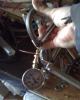
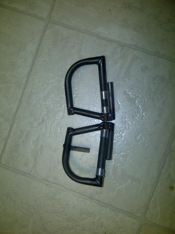
Picture of your pedals
in Avid Model IV
Posted
Here are some pics of pedals in my plane and on a test stand. You will see a few avids flying and using this design. Effective and easy to install but not easy to build .