Activity Stream
Posts Activity Stream
-
-
-
With factory wings, you should have a lot shorter build time.
But beware of extreme modifications - that can drag it out forever, or at least a lot longer - believe me, I'm there!
EDMO
-
Depending on your skills, I'd estimate 800-1200 hours to build.
The main thing is to do something, anything - even sweep up around the project, every day. This keeps the juices flowing and progress going.
-
the plane is a avid mk4 with factory built wings, the previous owner didn't make much progress, I have owned a few light sport planes kolb rans s12 kitfox2 but I didn't build them, I did recover the wings on the kitfox when I replaced the wing tanks. thanks looped
-
-
You might find the attached Avid Mk-IV W&B calculator entertaining.
do I have to put +1.5 and -146 in the arm to make it work I have a mark IV with a VW engine and 297 on left and 297 on right and 55 on the tail thanks randy
-
I understand this is a hard question to answer due to all the different variables . i am wondering how long it has taken you to build your planes ,I will pick up my kit on Saturday and am wondering what a reasonable build time is for a first time builder. thanks ,looped
-
I don't know about any further analysis, but that is the system in use from the IV through the current SS.
Avid used a plywood insert.
-
Kitfox only went to the insert after the integral I-beam spars were gone. I wonder if a comparison bending analysis was ever done.
Someone said or wrote that Dean flew the early Avid .065 spars at 1500 gw - was this without inserts?
EDMO
-
Kitfox does 1550 gross with .065" spars and the same 60" long "I" beam insert as the rest of their planes. It's a landing gear change to increase the gross.
-
I'm a Harley rider and have thought of those shocks before too. They would need to be used with a bellcrank type do system to multiply their travel.
With a Grove retrofit, the bungee truss is no longer an issue for strength. As shown in Doug's "taxiing incident" the door trusses are where the failure will occure. That is what I did the modification I did to my mangy fox project. I doubt very much I will ever to any extreme stuff that you guys out west do, but this will add a ton of strength.
http://www.avidfoxflyers.com/index.php?/topic/709-classic-iv-restoration/?p=10266
-
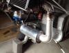
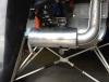
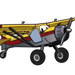
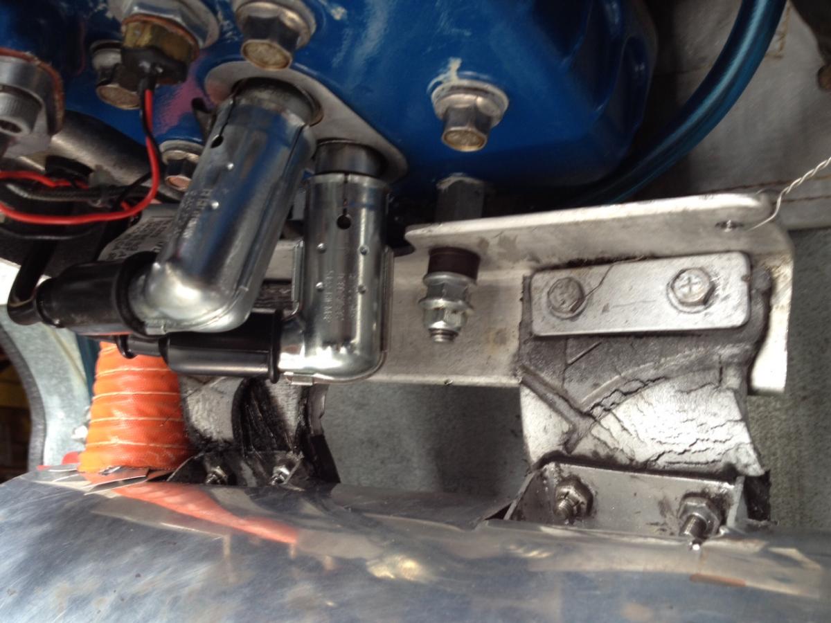
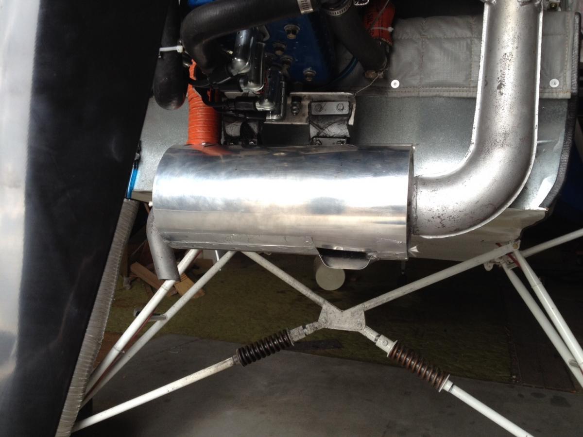
Thanks C5, Those standoffs were something I was looking for, and that engines exhaust mount is better than the system I have so thank you, I will try and be a little more civil in my posts from now on. How well does the exhaust heat work, I have a couple of old motorcycle radiators and robbed some computer fans out of junk computers for a heat set up that I was going to use. I learn more about the aircraft from the pictures you guys are sending, one picture can answer questions I hadn't thought of yet.
I would think that there wouldn't be any problems with the mount, If you look at some OEMs and what they hang off the engine that would be about the best way to mount the exhaust, and I love the low dollar approach of the tire tread to hang the muffler with.
http://www.aftermarketcyclepartsnation.com/Kimpex-EXHAUST-BALL-JOINT-ASSEMBLIES-detail.htm?productId=9846004#/0 this is what I was thinking you might need to replace, they do wear out
-
I know that you asked the question because you already have that engine, but did you get a chance to see what they are doing with the Yamaha engines over there? 118 lb fuel injection engine and little less if you get the carb models, In upper Midwest, these sleds are becoming throw aways now, the engines are still alive but we rarely get the snow that they need to keep a snowmobile alive, so they destroy the suspensions and seats but the engines are living on. I have been flipping a coin about switching engines, but I have too many projects as is, I have decided that I need priorities and my old Greyhead is going to power my plane until I get another built. Then I will look at buying the Yamaha Engine to Build, By that time I should have the discipline not to use all that horsepower.
I think you will find that almost anything is doable, I checked over on Southern Airboats and found someone who had done your conversion, but you had better have the tools to do it yourself otherwise you would be better off buying a used engine with a good case and switch your internals.
-
Doesn't Just Aircraft claim up to 1500 lbs on their aircraft, they were using a .063 or .065 spar in their aircraft. Dean Wilson knows how to design an airplane, they were originally tested to a load way over the gross weight, but there is a difference between Flying and where you land, as has been stated before it is more than just the wing that makes a plane capable of handling higher loads. There has become a lot of stories on this design and some truths that have become facts, I would love to spend a day talking with the man, and I wonder if He knew the plane he designed 30 years ago would still be a major factor in aircraft today.
1 person likes this -
I have 2 of those Harley shocks sitting on the bench, they are heavy, and the wheel travel on a Harley is only 4 inches with the ratio included, I don't know how they would help, but I figured if we were going to talk about them, we should keep that in mind. A Softtail Harley weighs over 600 lbs depending on the model, and with passengers weighs up to 1200 lbs, and uses 2 shocks to support the load, they are designed for constant motion where we are looking for something that moves only occaissionally. Just some parameters to add to the pot,
-
This discussion is driving me bonkers.
Why, it is making points for the Grove gear mainly due to it's simplicity in spite of adding approx. 12 pounds over original gear and who knows how abusive Grove gear is going to be to the longerons and bungee truss when the going gets really rough.
I really want Cub style gear (if it is really better than the alternatives for rock bashing) and I have spent weeks researching how to do it correctly on my Model 2 Kitfox.
I do not like the advice I have been given.
My Kitfox's longerons, seat-bungee truss and lower door frames need to be replaced with bigger tubing and more bracing and that is major surgery.
And why do I want to consider all this?
So I can Adventure fly to where airplanes were not intended to land.
What better thing to do with an airplane that I could almost drive there faster than fly.
My wish for Joey's thread is to come up with a gear design that requires minor surgery to the fuselage and will take much more bashing than stock gear.
FoxDB's post #14 regarding how the compressive loads are directed towards the longerons needs to be addressed.
Trackwelders post #8 regarding triangulating the Cabane V is right on IMO.
A simple tube across the top of the V would help both longerons to share the loads and minimize the longeron twisting I believe.
Notice Joey's 9th photo of the front view of a white Rans S-7 with Roberts Gear.
The gear and cabane get bolted to their own brackets so the compressive forces do not try to twist the longerons.
Both the Highwing and Joey's gear use the same bolt for the front gear leg and Cabane.
This makes the install very simple since new brackets do not need to be welded on the longerons.
This also becomes a compromise because I feel we really need bigger than 1 inch diameter front gear legs to prevent Joey's front leg collapse.
They say tubing diameter has more to do with compressive strength than tubing thickness.
My Kitfox brackets are 1-5/8" inside. It would be challenging to pinch down 1-1/4 tube and weld it to a slug and not exceed 1-5/8's width let alone room for the Cabane tabs to go inside the Brackets.
John Rodgers from Homedale has a unique style cabane gear he built for his Model 4 Kitfox.
His Cabane V if you can call it that, is welded to a reinforced seat truss and he uses 1-1/4 diameter front gear leg.
Anyone know how John Rodgers gear works.
Enough for now.
I am counting on you engineers.
-
I was talking to another Avid buddy of mine yesterday and he shared with me his exhaust mounting set up. He put two studs in to substitue the head bolts. Pretty simple set up. I think I could do something like this relatively easy. Anyone know of any issues with having something hanging off the head bolts like that? If you used a stud and properly torqued a jam nut I don't see why it wouldn't work. He has a pretty sweet muff heat set up too. It's a small world... I had a deposit on this plane once upon a time.


-
DB thanks for sharing your information. This is the type of conversation I was hoping this thread would generate. I think the reoccuring theme here is don't make poor landings....I know mine would still be on there if I would have said naw....I better not land that spot that's at 6000ft on the side of mountain that's full of rocks and gopher holes, 20 miles from the nearest road, with all my camping gear on board, by myself......I made a laundry list of screw ups that day...I survived, damage was minimal, it makes a good story, and I learned alot so about all you can do is press on and try to not do it again.....


-
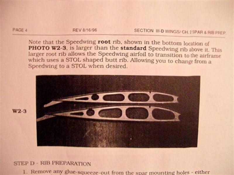
Please place everything wing related in this thread. The following is from Doug Holly.
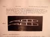
I built a custom hybrid 'long heavy hauler speedwing' for my Avid+, hoping to have the best of both worlds. I used and followed the Mk-IV Heavy Hauler material and construction method (see both Leni's .pdf drawings and the wing difference explanation below), however, I substituted the flat-bottom Speedwing ribs instead of the under-cambered Heavy Hauler/STOL ribs. The root rib on Avid Speedwing/Aerobat planes is a special 'transitional' rib that matches up to the butt rib (which was always HH/STOL shaped to allow folding wing clearance). In the attached pictures, you can clearly see the differences between the speed and under-cambered rib profiles both on and off my wing.
Also keep in mind, 'Heavy Hauler' was the name attached to several Avid models. A Heavy Hauler B or C model was 1050lbs M.T.O.W. A Heavy Hauler MkIV was originally 1150lbs and then, to compete with the Kitfox 1200, "re-marketed" as 1200lbs. This is the reason one has to be careful around Avid gross weights and wings. In addition to wing length, material and construction differences, the under-cambered HH rib profile was very different from the flat-bottomed Speed rib profile.
In general, Avid Flyer wing differences extend to spar thickness, spar length, lift strut o.d. diameter, airfoil, rib spacing and drag tubes. All wings called for (2) nose ribs between wing ribs, though an additional nose rib per bay is often added on the Speed and STOL wings due to their wider rib spacing. Here are the basic differences between the (4) Avid Flyer wings explained:
Speedwing: .065" thick 2-1/2" o.d. spars; 108-1/2" spar length; 3/4" dia. lift struts; Avid flat bottom airfoil; (7) ribs ~ 18" o.c.; (3) 1/2" dia. W-2 alum drag tubes; (3) W-3S Short 5/16" dia. alum root rib brace tubes; (1) W-4 Short 1/2" dia. alum root rib brace tube; (1) W-3L Long 5/16" dia. alum tip rib brace tube*; NOTE: Wing tank replaces (1) W-2, (3) W-3S and (1) W-4 alum rib brace tubes at the root end of wing; Key rib dimensions (long rib flaperon hinge) are 35-1/2", 71" and 106-1/2" o.c. from tip rib
Mk-IV HH: .083" thick 2-1/2" o.d. spars; 144" spar length; 7/8" dia. lift struts; Avid undercamber airfoil; (13) ribs ~ 12" o.c.; (1) 1/2" dia. W-2A steel drag tube; (3) 1/2" dia. W-2 alum drag tubes; (3) W-3S Short 5/16" dia. alum root rib brace tubes; (1) W-4 Short 1/2" dia. alum root rib brace tube; (1) W-3L Long 5/16" dia. alum tip rib brace tube*; NOTE: Wing tank replaces (1) W-2A, (3) W-3S and (1) W-4 alum rib brace tubes at the root end of wing; Key rib dimensions (long rib flaperon hinge) are 35-1/2", 71", 106-1/2" and 142" o.c. from tip rib
STOL: .065" thick 2-1/2" o.d. spars; 144" spar length; 3/4" dia. lift struts; Avid undercamber airfoil; (9) ribs ~ 18" o.c.; (4) 1/2" dia. W-2 alum drag tubes; (3) W-3S Short 5/16" dia. alum root rib brace tubes; (1) W-4 Short 1/2" dia. alum root rib brace tube; (1) W-3L Long 5/16" dia. alum tip rib brace tube*; NOTE: Wing tank replaces (1) W-2, (3) W-3S and (1) W-4 alum rib brace tubes at the root end of wing; Key rib dimensions (long rib flaperon hinge) are 35-1/2", 71", 106-1/2" and 142" o.c. from tip rib
Mk-IV Aerobat: .083" thick 2-1/2" o.d. spars; 108-1/2" spar length; 7/8" dia. lift struts; Avid flat bottom airfoil; (10) ribs ~ 12" o.c.; (1) 1/2" dia. W-2A steel drag tube; (2) 1/2" dia. W-2 alum drag tubes; (3) W-3S Short 5/16" dia. alum root rib brace tubes; (1) W-4 Short 1/2" dia. alum root rib brace tube; (1) W-3L Long 5/16" dia. alum tip rib brace tube*; NOTE: Wing tank replaces (1) W-2A, (3) W-3S and (1) W-4 alum rib brace tubes at the root end of wing; Key rib dimensions (long rib flaperon hinge) are 35-1/2", 71", and 106-1/2" o.c. from tip rib
* Applies to wings with wire trailing edge only, not required with metal trailing edge.
Be aware that wings with the exact same descriptors, ie., STOL wings, may have different Gross ratings depending on when they were sold/built. One thing is certain, there were so many combination of fuselages and wing components bought, built, or cobbed together over the years it can be very difficult to determine exactly what Gross you have unless you physically measure spar thickness, tubing diameter, or even cut a tube to verify wall thickness.
-
That's why te forum took a dump a few weeks back. Doug I'm going to move the wing info into the files and forms area. Sure there's lots of folks who have needed access to that data at some point.
-
SkyPirate,
I believe it defintely would have gone slack at the outside. There is a bending moment on the axle which would transfer to the gear leg. This is a big contributor to bucking of the gear leg as shown in the picture posted by C5enginger. The best defence is to increase the diameter of the gear leg as I don't believe the tire could be any closer to the leg.
Dave
-
-
Fox if you could have put a couple points about 3 inches long ,,1 at top of forward gear leg 90 degrees to leg and one at the bottom and then put a string between them so you could see it parallel with the forward gear leg from the front,..I wonder how much it would have slacked at impact
-


History of the Avid
in Files and Forms
Av8r3400
Posted
(Brett Mc Kinney bought Airdale in 2007)
Interesting to see that he feels the "group build" is what put Skystar over the edge into bankruptcy. I know a couple of those guys. Many of them lost thousands if not tens of thousands of dollars.