NorthIdahoAvidflyer
Contributing Member-
Content count
687 -
Joined
-
Last visited
Posts posted by NorthIdahoAvidflyer
-
-
-
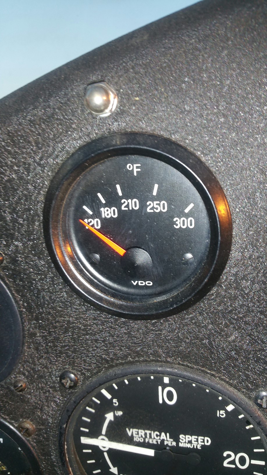
I'm running a GSC three blade. I ran it again with the same results. I kept a closer eye on the temps. When I shut it down it was pushing water slowly into the reservoir. The gauge is a VDO gauge with markings at 120, 180, 210, 280, 300. The engine was warm. Im waiting for cooler evening temps to run again.
-
Thank you Jackak. I'm not sure my gauge set up is reading correctly either.
-
I started my 582 for the first time today. After warming it up and checking everything out I started the break in regiment. All went good until I got to the 30 second 6500 rpm run then the temps shot up very quickly. I was forced to shut it down. I have to admit I should have looked up the exceptable temperature for this engine before starting. It went over 200 before i noticed it. This is a Grey Head 582 with a thermostat installed. OAT was 90 here today and my plane has the front mounted side radiators. Cowl was off. VDO car gauge. EGT's got high only at full power runs. They ran around 1000 degrees during the 4000 to 5000 runs.
Would like to hear what you have for advice. And what I should do from here.
-
Love it. Wold he be intereaten in making more?
Vance
-
 2 people like this
 -

 1 person likes this
 -
Do you guys remove the spark plug gasket on the spark plugs with the CHT sendors? If so how do you get those gaskets off. I remember reading somewhere about them being removed. I can't find anything on it now.
Thanks
-
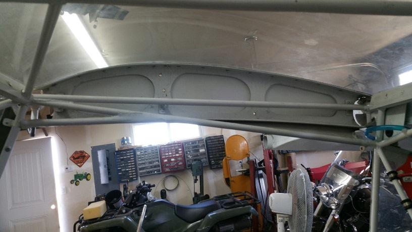
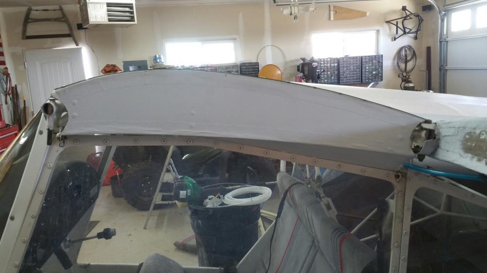
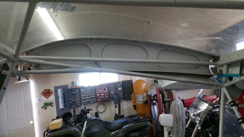
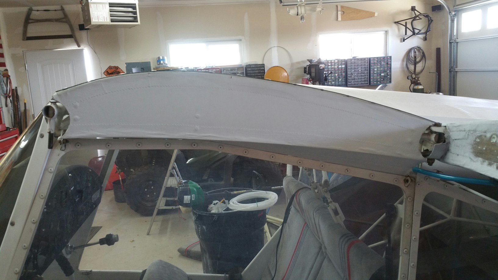
The fabric is not glued real well to the rib. I believe poly product was used.
Vance
1 person likes this -
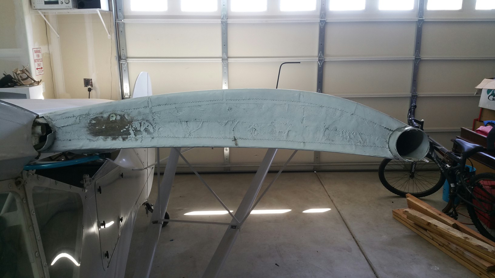
I decided to try making a place on the end of the wing to monitor fuel levels instead of trying to mess with sendors and installing another gauge. The builder covered the cabin rib with fabric. I would have to cut out the fabric in the center rib holes on each side to gain access to the end of the wing tanks. My question is.....should I just cut a slot in the fabric or cut all of the fabric out of the center hole? Pictures attached.
Vance

-
It's been a while since I posted. I've been doing little things but mostly working on my tractor. New clutch and an unplanned blown head gasket. Turns out the head had a crack between the injector and intake valve on the center cylinder.
So the Avid fuel tanks are cleaned and ready for fuel. The tanks had little to no contamination.
When one tank was laid up they didn't clean the fiberglass away from the outlet holes in line with the inserts. The builder didn't realize this and put the outlet and curtis valve in crocked. I was able to clean them up with a dremmel and tap.
My problem is the 90 degree outlet is not tight when at the right position and if I try and make another complete turn it bottoms out leaving the 90 aiming at the end of the wing. Have any of you had this problem and what did you do to fix it.
Thanks
Vance
-
John, thanks for the post. Sorry about the meeting this month. We normally do not have a regular scheduled meeting the month we do the Treeport Fly-in. I guess John wasn't aware of that. We should be back on track with 4th Saturday meetings next month.
I live in Post Falls and would love to have you over to check out my projects. My Avid should be flying soon.
Yes, Terry is a great guy and can go on for hours about his Military flying. He has had some amazing experiences.
Send me a private message on here and I'll forward you my contact information.
Vance
")
-
That's a great idea Jim. I could fabricate something like that easily. Maybe use a pointer.....hmmmm.
Sounds like another project. -
-
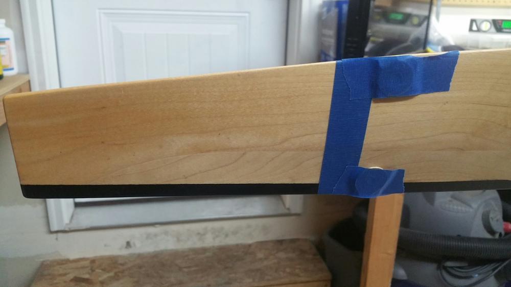
So after figuring out the proper angle I set into setting this prop up. This is my third GSC prop and I know some people don't like them but I have had good luck with them. It's been years since I had to set one up and I'd forgot a few things. It all came back once the prop was mounted on the gearbox.
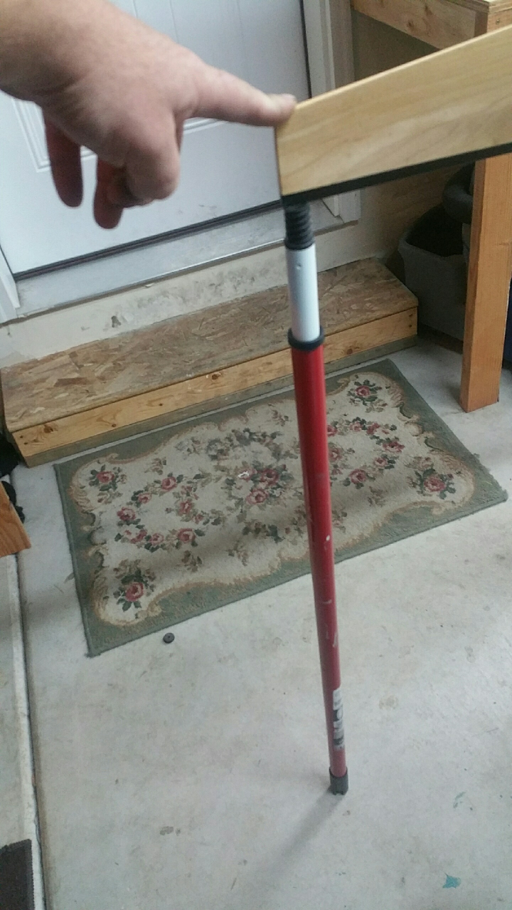
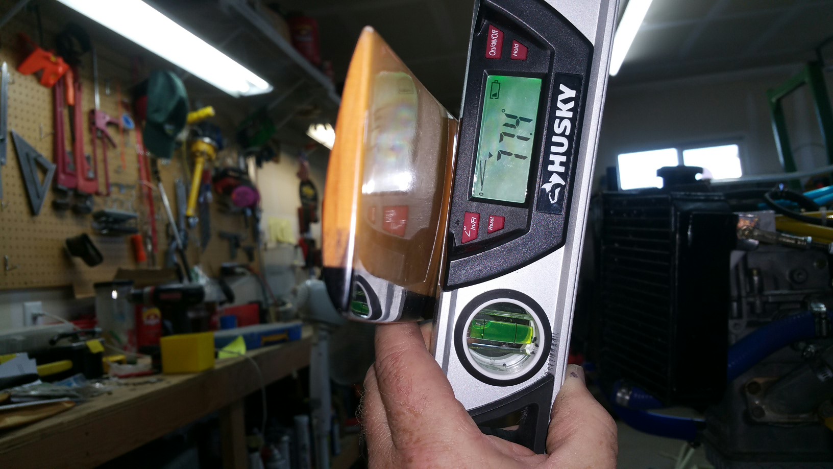
Leveling the face of the prop was easy. The location to pull the angle from was 8 inches in from the end of the blade so I marked that using an adjustable square and a pencil. With the marks in place I used painters tape to create a fixed location on each blade. Since the back of the blade is curved I had to tape a washer to the top and bottom of the mark. This gave me a flat place to set the electronic angle gauge. The instructions said to bring the blades to a like location to set the angle. I used an adjustable paint stick to set under the end of the prop so I knew I was at the same location each time. After all the blades were set I torqued the hub bolts per the instruction. All the blades held their set at 77.2. I checked the tracking and it looks great. It should be a runner. We shall see.
-
I think you are right and no the other end is the same wigth to except the aileron control tube. I spaced it with washers and it looks and works much better.
-
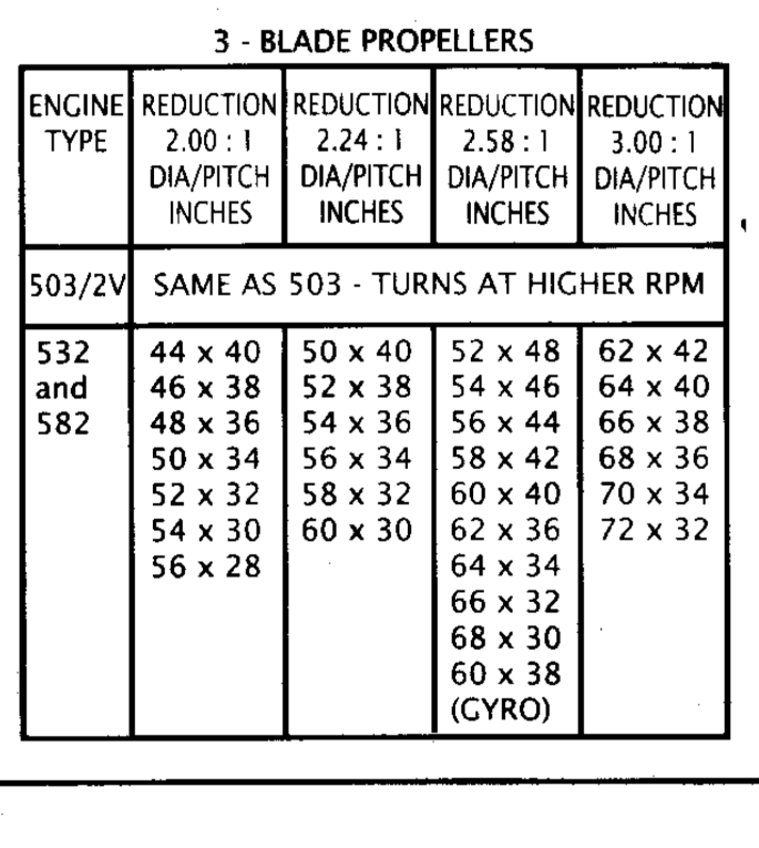
I read through the directions and figured it out. The plans call for setting the prop blade angle on a table laying at zero degrees. The 34 is the pitch in inches as determined by the factory. You have to apply this to their chart to figure the angle. This angle is given from zero degrees and must be calculate from 90 degrees if the prop is mounted on the engine. So 12.75 degrees minus 90 degrees is 77.25 degrees.
-
It appears I'm dealing with two different measurements.
-
-
It's hard to get an accurate reading like this. I also read the angle needed to be 34. This is nowhere close to the degree range I'm seeing on the electronic level. I am going to go back and look up the info again. I either got it wrong or they have thier own way of doing it measurment wise.

-
I'm open to suggestions. I have an electronic level. The problem is there is not a level surface on back of the blade for a phone or straight edge to rest security to get an accurate reading. The pictures I can find on-line show the angle being taken about 6 inches in from the end. I'll take a picture of what it looks like and post it.
-
-
-
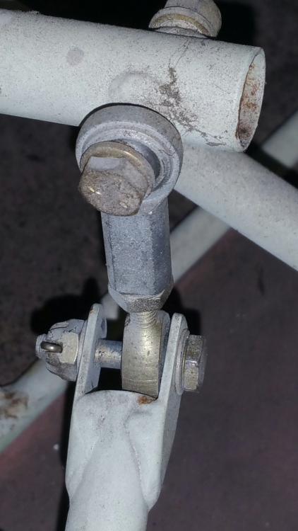
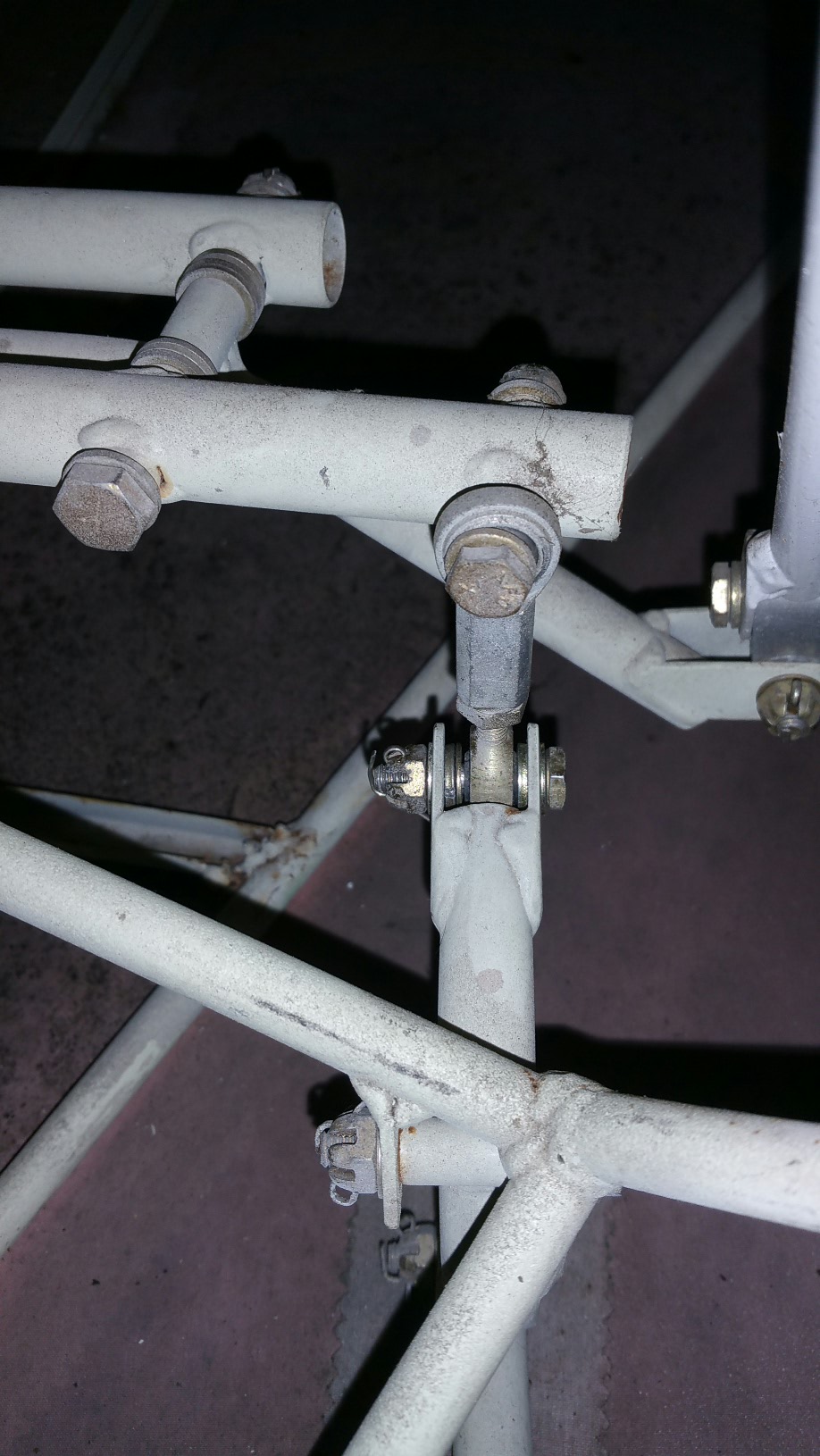
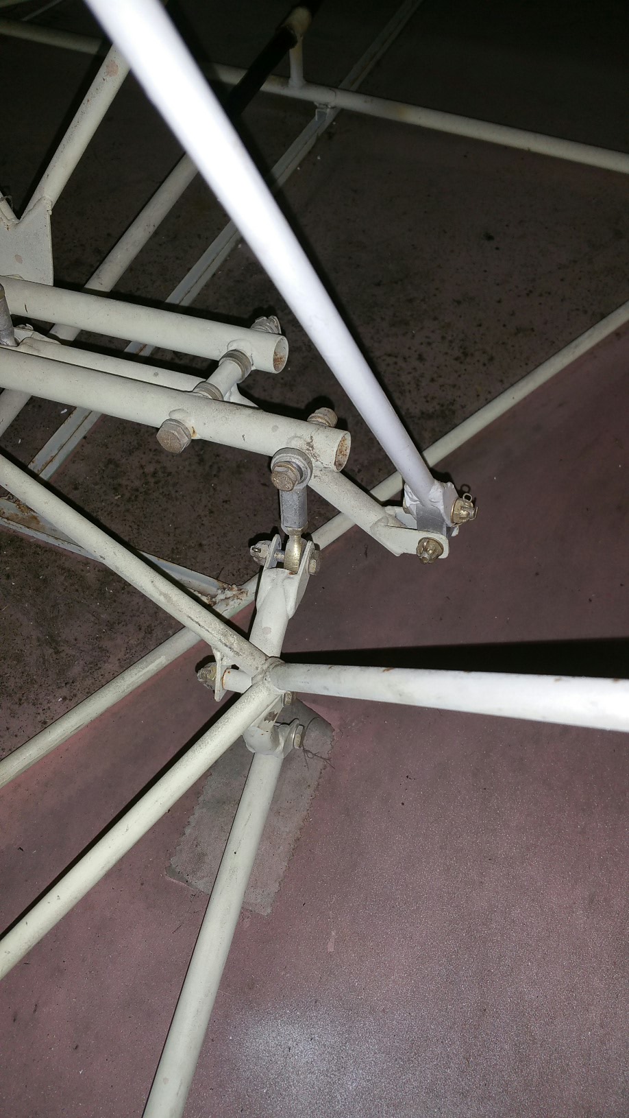
I spent better part of the morning going over the flight controls. Nothing really wrong with anything but a few safety pins changed and one jam nut tightened. I did find this a little odd. Pictures attached. I have to look over the plans but it seems there should be some spacers (washers) on the sides of this connection.


Break in high temps
in Rotax and other engines
Posted