
Willja67
Contributing Member-
Content count
174 -
Joined
-
Last visited
Posts posted by Willja67
-
-
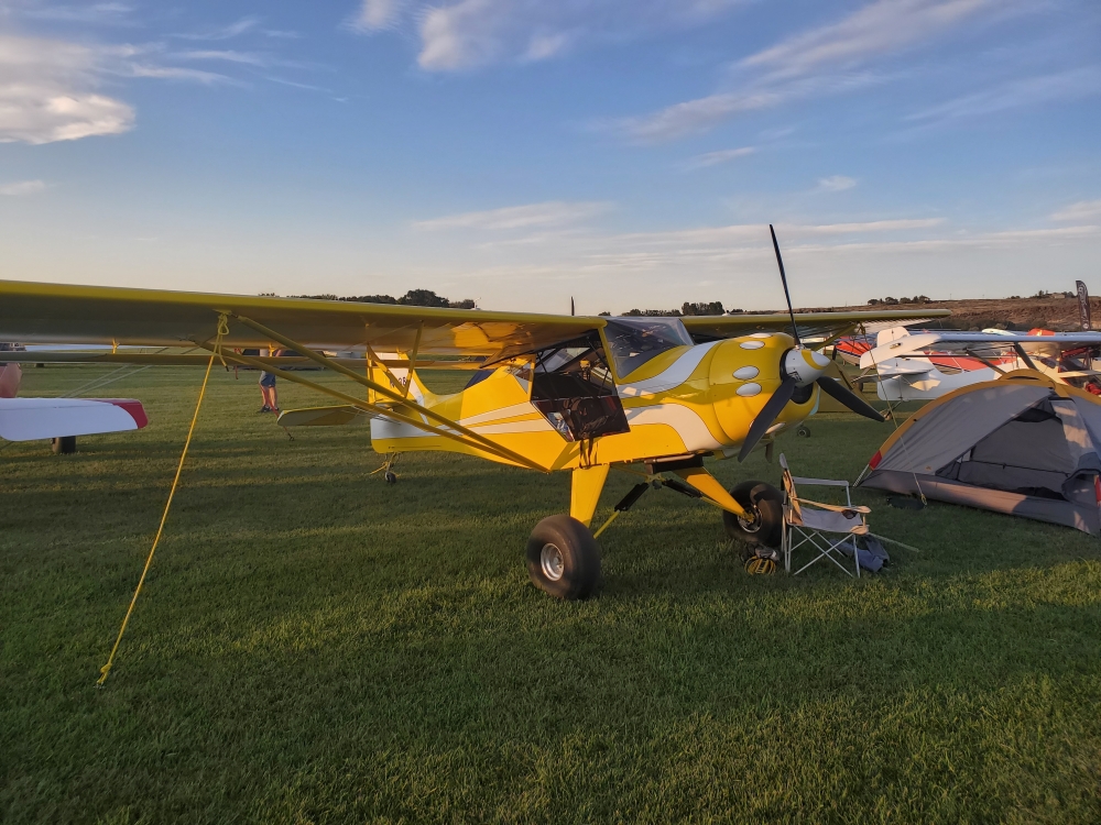
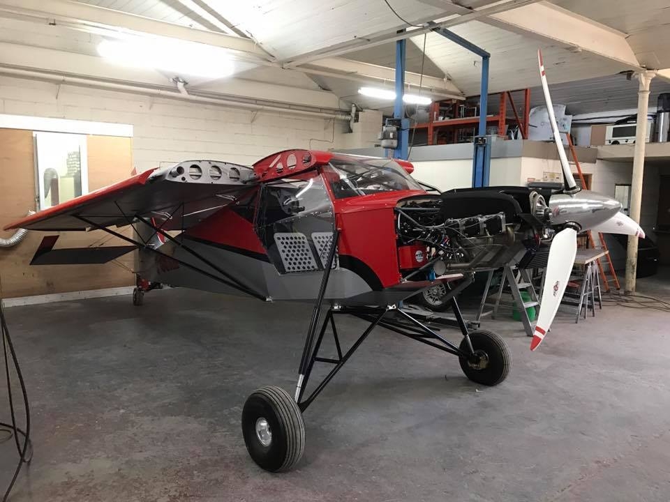
Interesting to note that he is not using their Hatz style bush gear but running shocks. I went to the Roberts Rage gear struts which uses a combination of shocks, bungees and gear legs of my own design and have been very pleased. No more bent up fuselage.
Actually, I don't think there are any damping shocks there. Amazingly enough that's the only pic I took at the whole event. I should have documented that plane from top to bottom because it was obviously built by a master but I was busy talking to him, then it was time for dinner then it got dark. I didn't make it the second day.
But pretty sure those are just dual coil springs over a tube to keep them straight.
edit
btw I'd like to see pictures of your setup
-
Spend a few pounds on streamlining and lower your throttle setting for the same airspeed, save a gallon an hour and increase your endurance by an hour or 2.
So 2 or 3 lbs = 20-30 lbs of gas that you don't have to carry.
I made it to the Kitfox factory flyin last month and talked to Lowell Fitt and saw his beautiful KF4 which has a lot of aerodynamic mods and that is basically his philosophy.
 1 person likes this
 -
Well Allen if I were you I'd have an automatic 90 lb useful load increase! I could stand to lose 30 lbs. I'm 6'1" and my ideal weight is about 195. The chart in the doctor's office doesn't account for guys like me i think. If I weighed what it recommends I'd be anorexic or have no muscle mass. I also happen to be somewhat claustrophobic. More especially i can't stand being in close proximity to other people for any length of time.
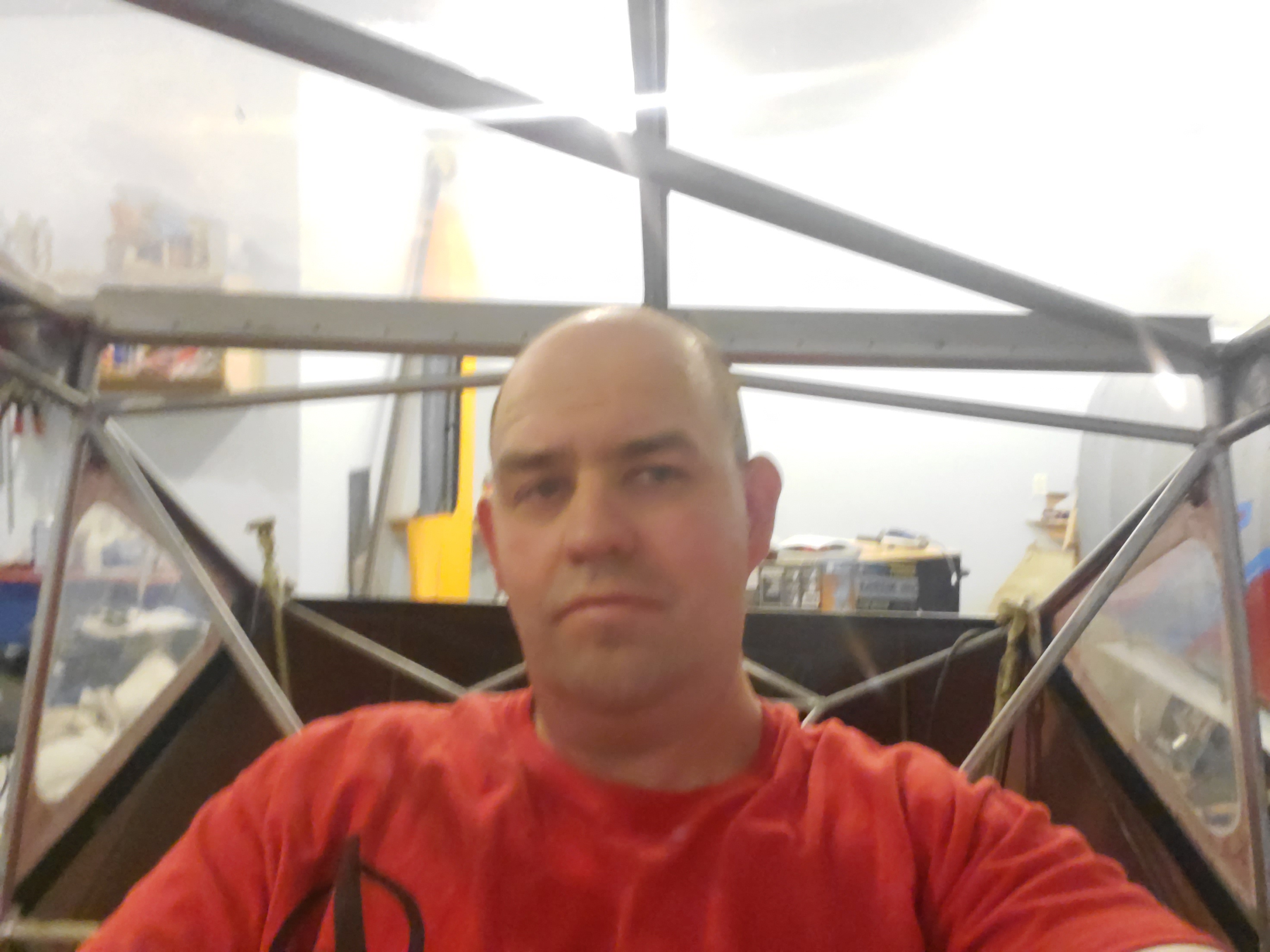
So I'm converting this to a single seater. No need to widen it. It would only add unnecessary weight.
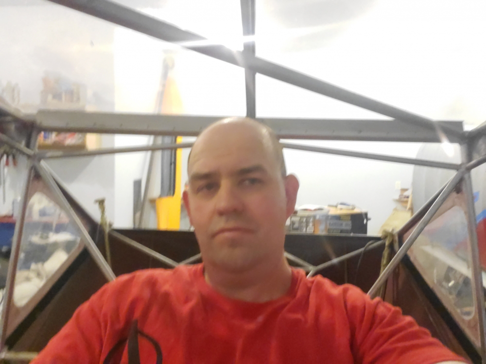
As you can see sitting in the middle there are only maybe 5 inches on each side. All you guys who fly with 2 people in these early foxes must be tiny! Even with an additional 3 inches of width at the shoulders I know I'd never be comfortable.
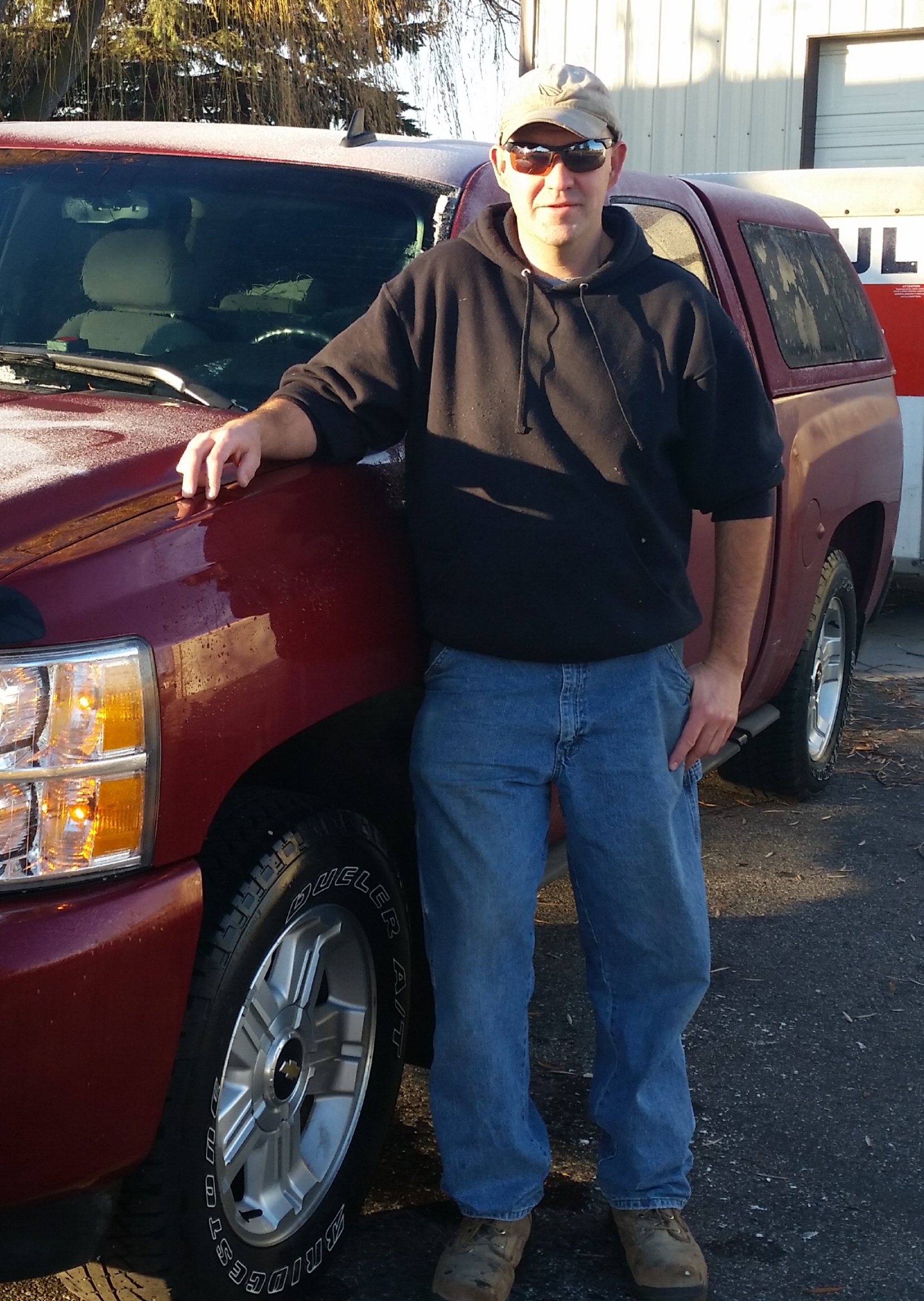
 And as you can see I'm not so fat that a sweatshirt can't hide it.
 I should add that i have a very specific vision for this aircraft that I know not all would agree with. That's fine i won't criticize your choices but I'm going to keep mine mostly to myself until I unveil it hopefully in time for Oshkosh.
There are some choices that have been made that there's no going back from (at least not easily). I'm building this plane for me and I'm well aware that I'm probably destroying the resale value. So be it, it's for me after all. I originally bought it to have something to fly but it needed work and I find that I love working on it and making it my own. I never would have fit in it in its original form anyway.
Oratex is going to be used to recover, unfortunately it probably won't net much weight loss since the original cover was unpainted polyfiber(polyspray only). It was a pretty nice cover job, whoever did it seemed to know what they were doing.
It came with a Garmin G5 and some backup mechanical instruments, which have been sold off. Only the G5 a mgl engine monitor this radio
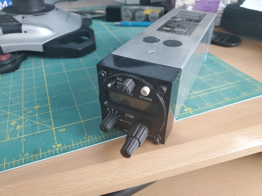 and room for an iPad mini. I'm not even going to have the panel go full width, just wide enough for the items mentioned.
 -
I'm doing a full tear down on my plane and looking at anything and everything that can go away on the name of weight reduction (safely of course). What purpose do the stringers serve? Could some of them be eliminated?
Sorry if it's a dumb question but I have never heard the reasons for having the wood stringers.
If i were to guess I'd say these might be reasons:
1. Improve the aerodynamics of the fuselage
2. Possibly structurally reinforce some tubes against buckling.
3. Add some internal volume if a control line or something needs to be run outside the frame.
4. Keep fabric from flapping too much.
5. Cosmetic
Anyway if i can lose a few ounces or even a lb or 2 that'd be nice.
-
Okay guys ever since I bought the plane I've been trying to convince myself that the rust I could see on the fuselage wasn't a big deal. With all the work I'm doing to this plane it's getting harder and harder to convince myself not to just bite the bullet and have a plane that I don't have to worry about for a long time.
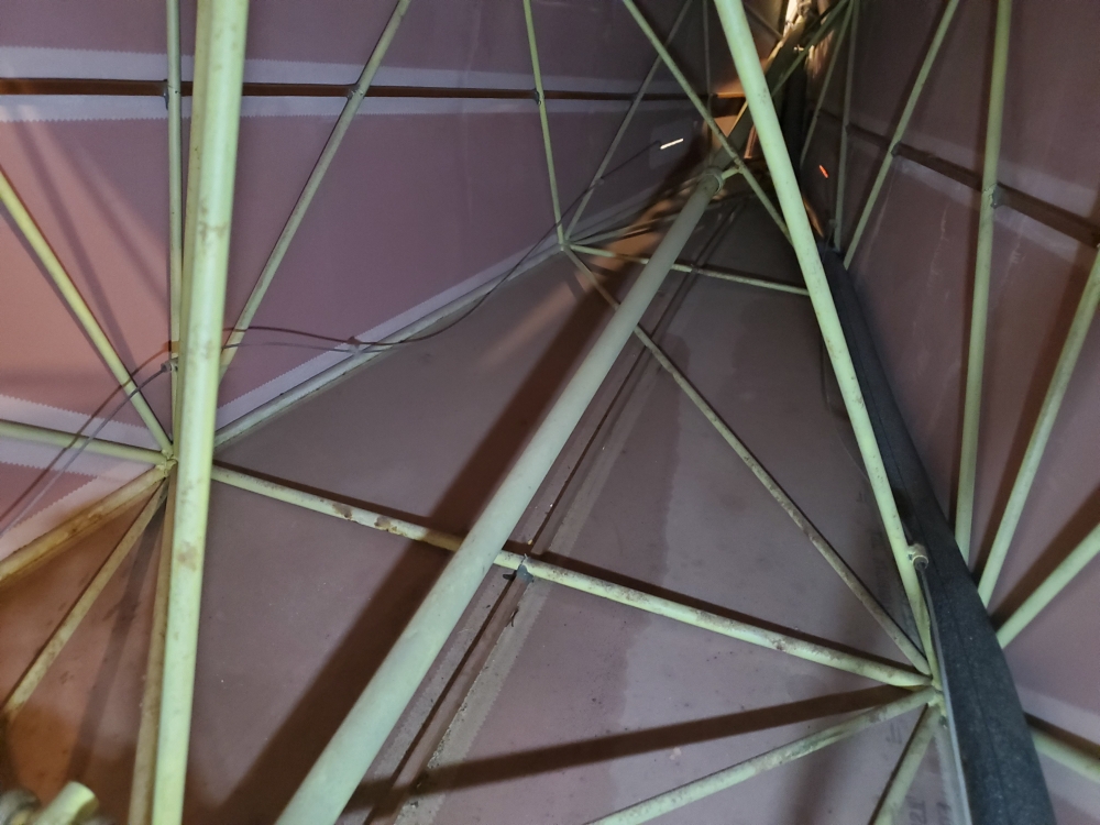
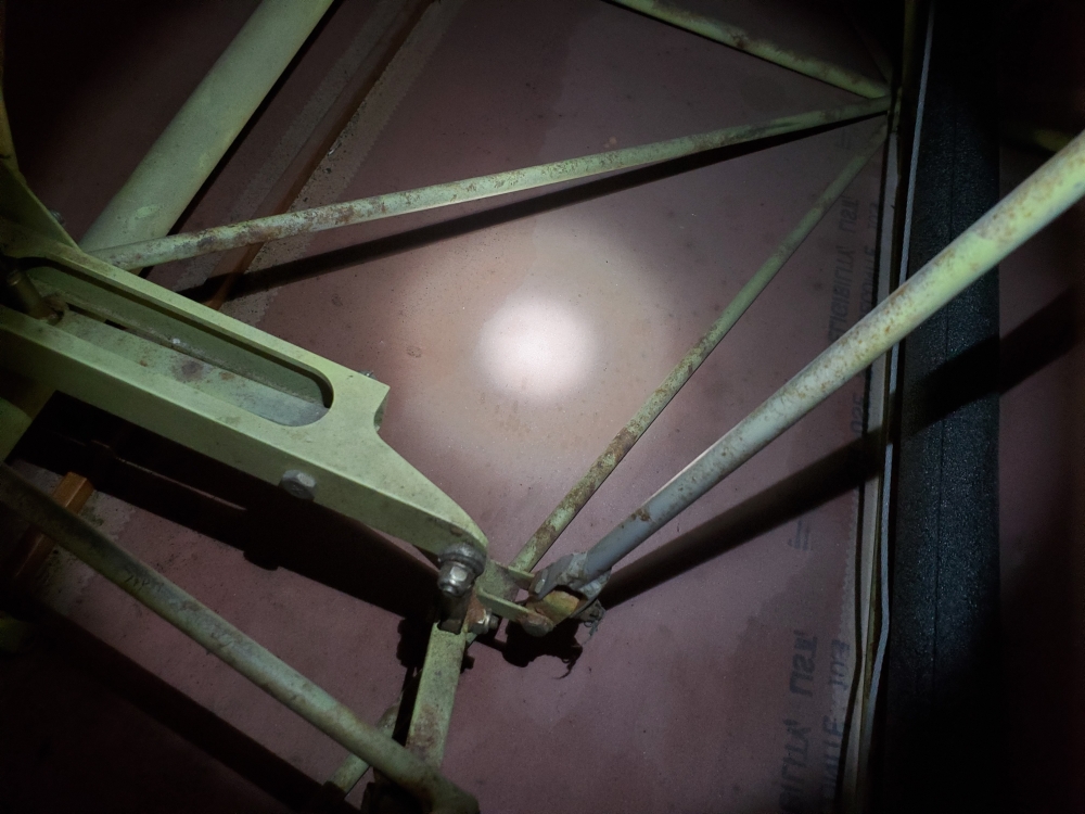
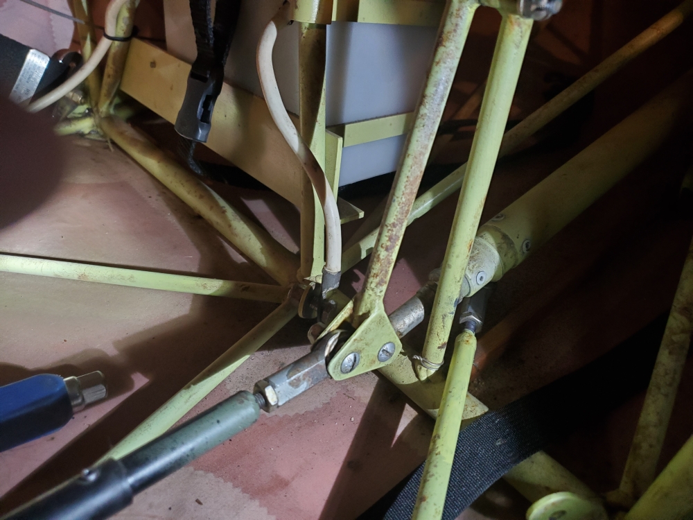 perhaps the idler is the piece that's doing the most to convince me. It just looks really rusty and it's just bothering me really bad. So pretty much committed to doing a full tear down and recover.
I'm also wondering about the fabric. I have the floorboards out and was just test fitting the rudder pedal back in and it fell forward and the rudder cable attach tab went right through the fabric on belly. It shouldn't be able to do that right?
Ok so here's where the questions start.
What's the best way to strip the paint and rust? Ive been looking at the sand blaster from Harbor Freight. Any reason not to go that route?
What's a good paint to use? It looks like it's got zinc phosphate on it now, and I'm thinking that didn't work so well. So what's a better option? Hopefully it's something that i don't have to spend a lot of money buying application equipment.
-
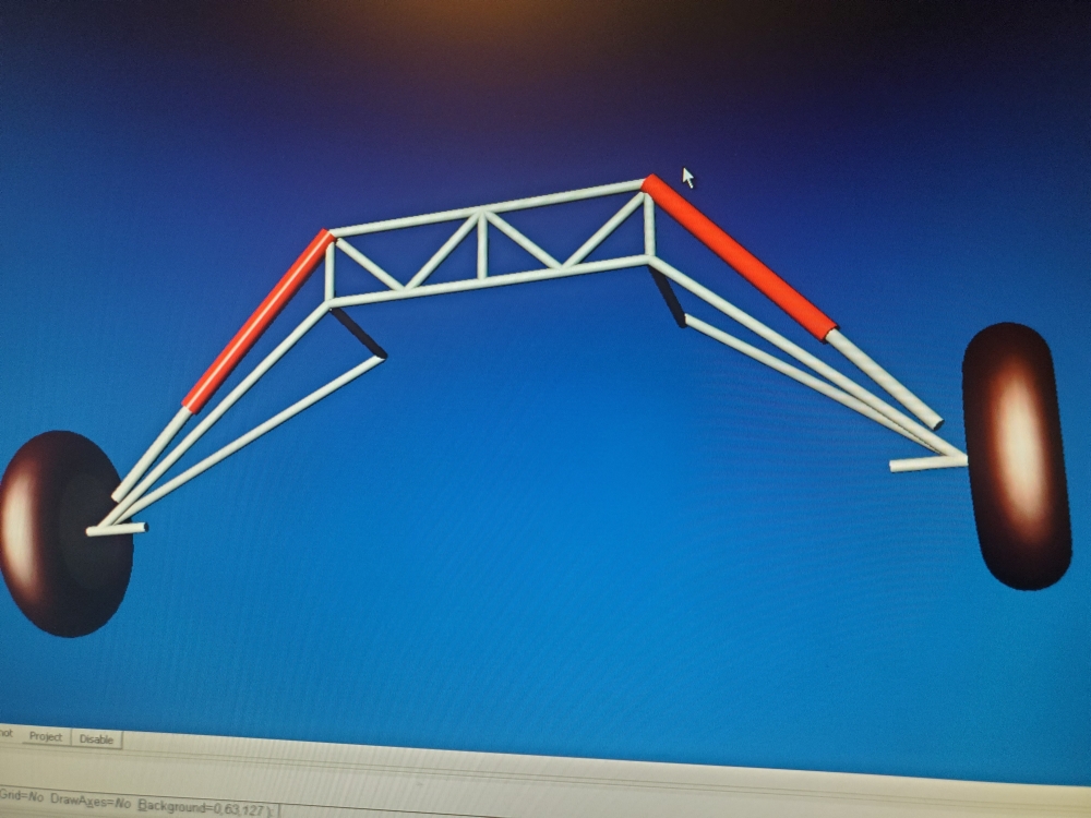
Just eyeball Engineering here since i don't know how to run the numbers anyway, but the tendency of a cabane spring gear to pull the lower longerons together is well known. My drawing of the seat truss might not be dimensionally accurate but the general placement of the tubes is. The tube that angles inward and down from the proposed upper shock mount location seems to my untrained mind to be better for that application that a cabane style landing gear. If that tube started at the bottom of the truss and angled upward instead methinks it would be better for the standard Bush gear as it would offer a little more resistance to pulling the longerons together.
Still not suggesting it's adequate for what i proposed just suggesting the geometry might be a little better.
I think the basic approach is correct but to get the geometry right we should look at Just Aircraft and their Highlander.
You could even go all the way up to the wing (and add a cross bar...).
That's actually the Super Stol not the Highlander. After i drew that first drawing I went back and got some more precise measurements off my plane and worked out the geometry. If you use a 32" long shock that only compresses 4 inches you can get 20" of vertical travel at the wheel. That would allow the wheel to hang down 8" further than the lowest it can go now with the bungee setup and and still have 12 more inches of deflection past the statically loaded point. With my engine and prop setup if i came down in a level attitude that still gives me 2" before I smash the prop. I imagine I'd probably come down more tail low than that.
Aside from the seat truss probably not being up to the task none of the shocks that i could find came in 32" lengths that only compressed 4". If you use a 32" shock the compression stroke is around 12" which means the tire could theoretically hit the bottom of the wing (of course the belly would hit long before that happened).
Given all the stories about collapsed gear that are documented on this site I'm thinking that some kind of suspension system with these kind of capabilities would pay for itself on your first hard landing.
-
Just eyeball Engineering here since i don't know how to run the numbers anyway, but the tendency of a cabane spring gear to pull the lower longerons together is well known. My drawing of the seat truss might not be dimensionally accurate but the general placement of the tubes is. The tube that angles inward and down from the proposed upper shock mount location seems to my untrained mind to be better for that application that a cabane style landing gear. If that tube started at the bottom of the truss and angled upward instead methinks it would be better for the standard Bush gear as it would offer a little more resistance to pulling the longerons together.
Still not suggesting it's adequate for what i proposed just suggesting the geometry might be a little better.
-
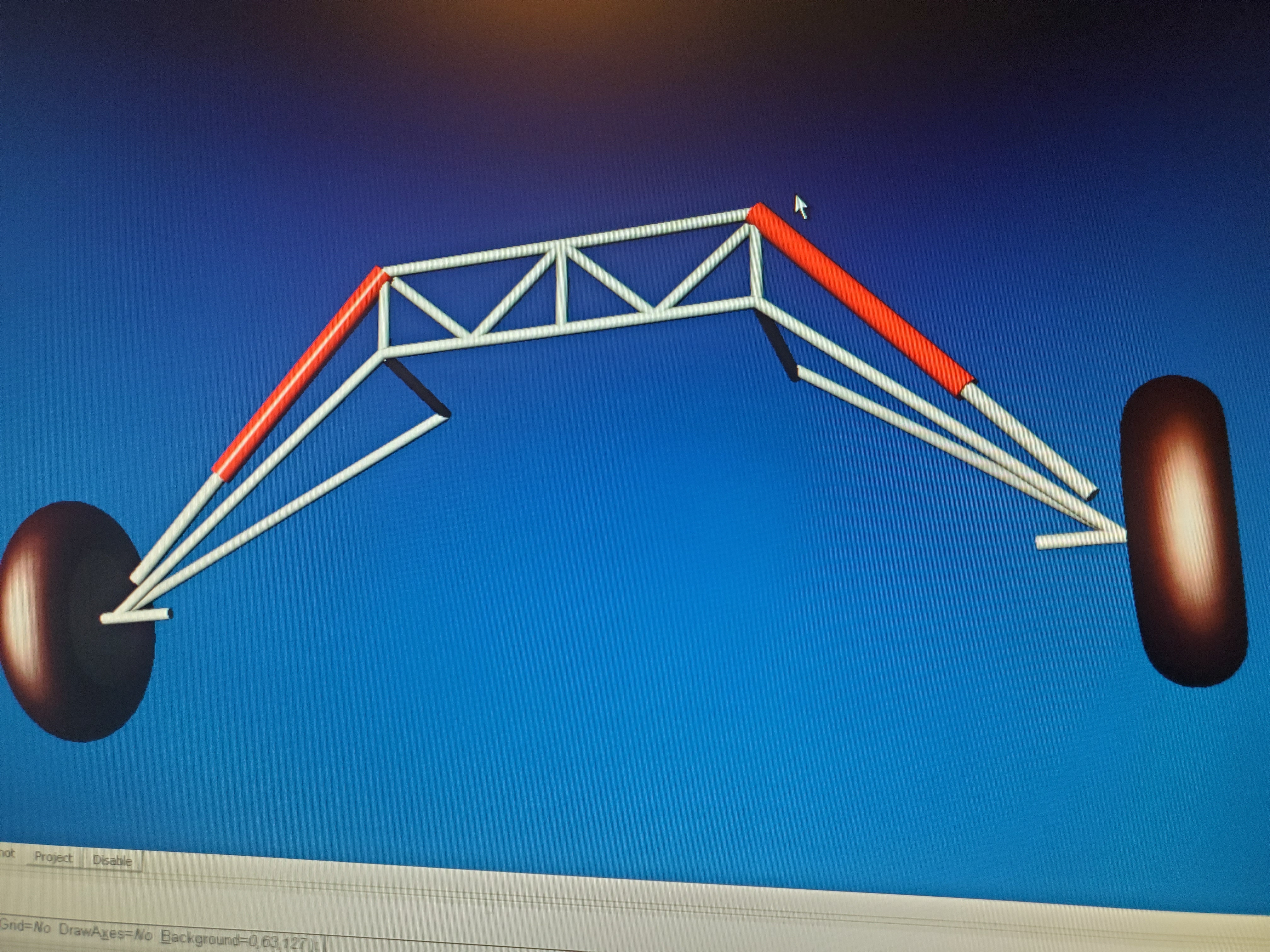
Had an idea that's interfering with my sleep. Had to draw it out before i forgot it.
Why keep the cabane at all? Run shocks from the axle to the top of the seat truss.
Problems i can see is that with a cabane a hard landing pulls the fuselage sides in, aren't structures usually stronger in tension than compression?
That seat truss obviously isn't anything close to accurate i just drew it to give the idea.
 3 people like this
 -
The guy i bought the plane from was a good 6 inches shorter than me but had the same inseam length in his pants. Ive got most of my height in my torso so i might not have to pull my knees up as much as you do. But my head is mighty close to the roof. I smacked my head real hard once in a DA-40 when we hit an unexpected downdraft. And i think my head is closer to the ceiling in the kitfox. A downdraft could well knock me out cold. Ive only barely contemplated raising the ceiling. Might be a necessity. I'll have to make that decision after the new sling seat is in.
-
I am 5'11", and have a hard time squeezing myself into the Avid C's confined cockpit. It seems my legs are too long, as my knees are inches from the top of the stick, and the rudder pedals with toebrakes contort my feet to the point where my lower legs cramp up. This is disconcerting to say the least, especially when contemplating an imminent landing! My slingseat is all the way back. So, you guys that are as tall as me or taller: how do you do it? Is the Mark-4 cockpit any bigger? My bird doesn't seem to want to fly well with feet off of the rudder pedals.
So you 6'-plus guys: how do you deal with this limitation? Or is this airplane only for shorties?
At least on the rudder pedals i have a solution. Should be fairly cheap and easy to execute.
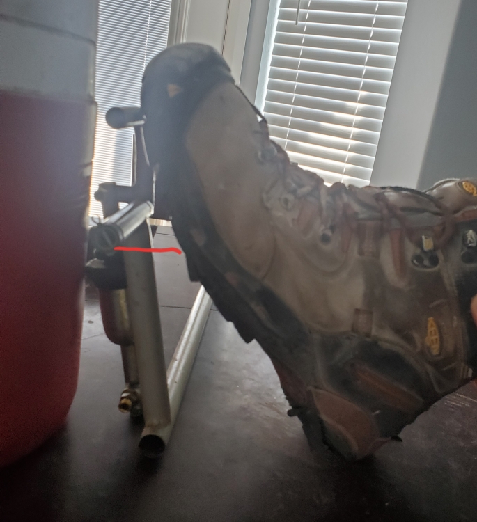
I'm 6'1" and have size 13 shoes. As you can see from the pic there's no way to get the rudder without pushing the brakes without uncomfortable contortions that I consider too dangerous to consider flying. Just too hard to correctly use rudder and brakes on a tricky landing.
Ive read the comment multiple times about tilting the brake pedal back and my solution accomplishes that in addition to improving the brake pedal/ master cylinder geometry.
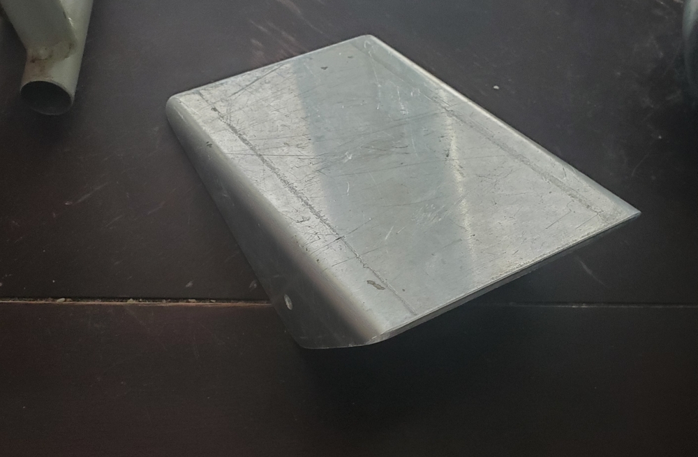
The above piece of aluminum is for another plane but gives the idea perfectly.
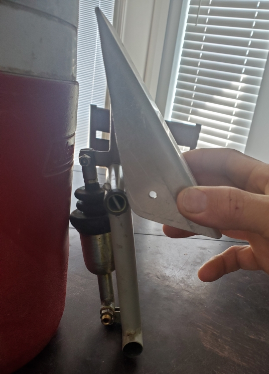 as you can see it parallels the bottom of your foot so you're pushing on the rudder and not the brake. It also gives significantly more mechanical advantage when activating the master cylinders. Matco recommends no less that 2.5 to 1. The stock setup on my KF1 is roughly 2 to 1. Not shown on this piece of aluminum is an arm that will extend to the master cylinder.
 So I'll kill 2 birds with 1 stone. I don't have the seat or floor boards in my plane right now so i haven't drawn up the final design yet. But I think this ought to appeal to the minimalists like Allen out there. A few bucks for the aluminum, and a piece of steel tube to act as a axel, some washers and a cotter pin or 2 and some time cutting and shaping.
Edit:
I never ran the engine before i tore the plane down but the previous owner said the brakes would only hold the plane to 75% throttle. So I'm hoping for better than that with these new pedals.
-
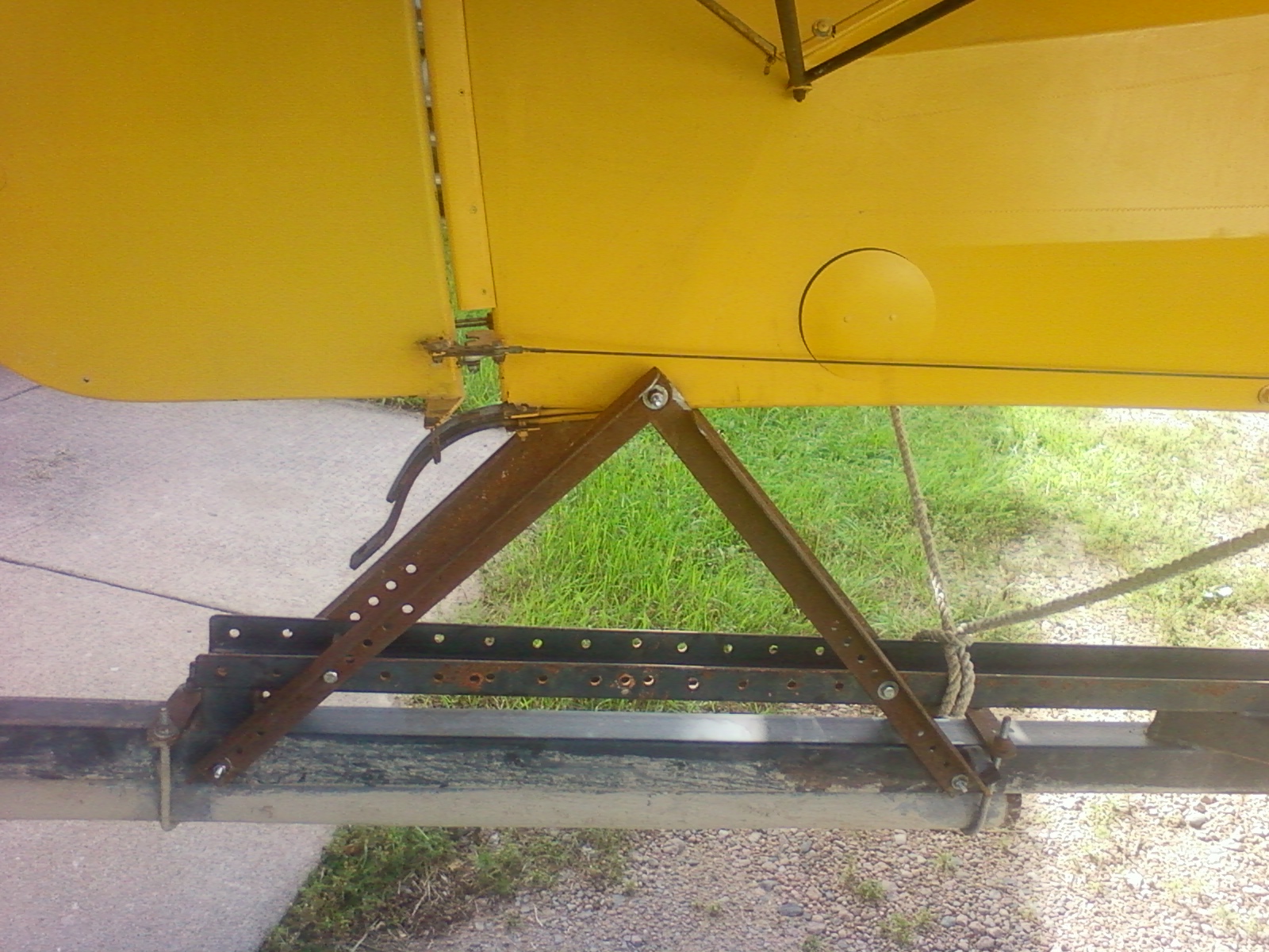
Mostly just knowledgeable where ive screwed up or my digging has found little nuggets. Id also look at your tailspring. Looks like mine, meaning it's sprung. Should be angled more downwards. You don't have any support for the aft fuselage on that trailer. All the weight of the wings on the tail could well have overloaded your spring.
-
Just make sure to spread the wings before taking it off the trailer.
-
Title says it all. Pretty eye opening
3 people like this -
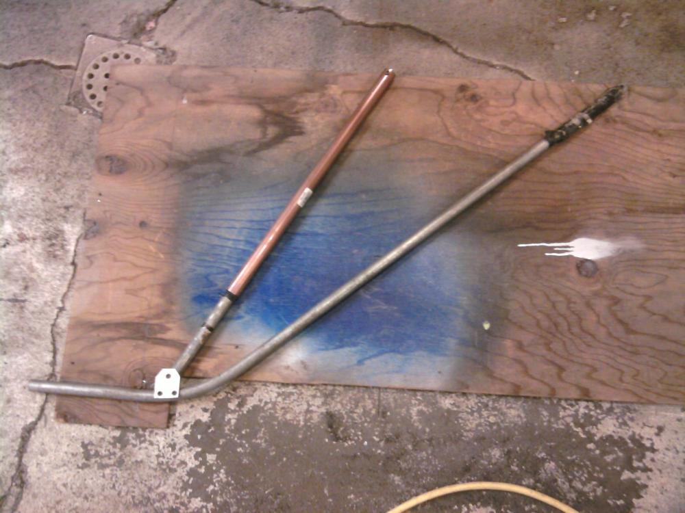
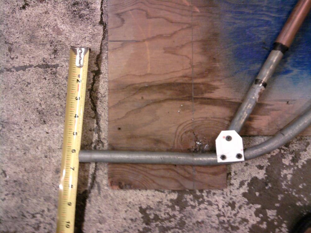
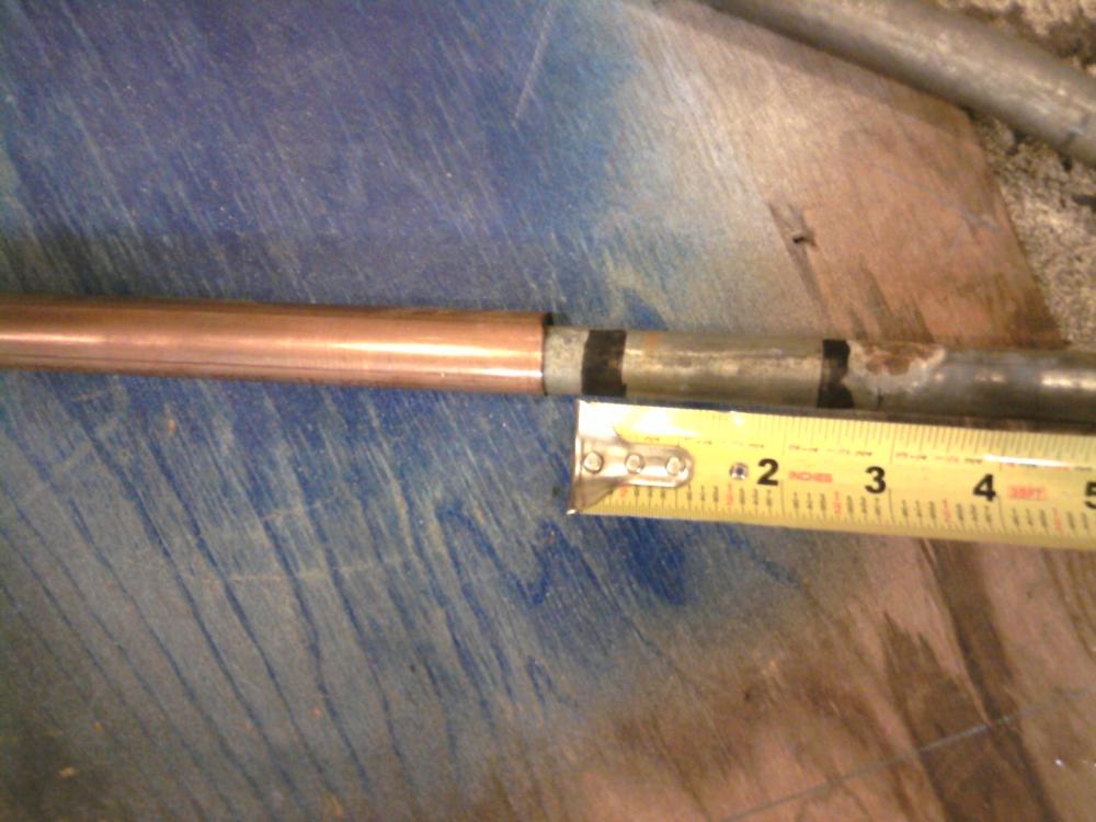
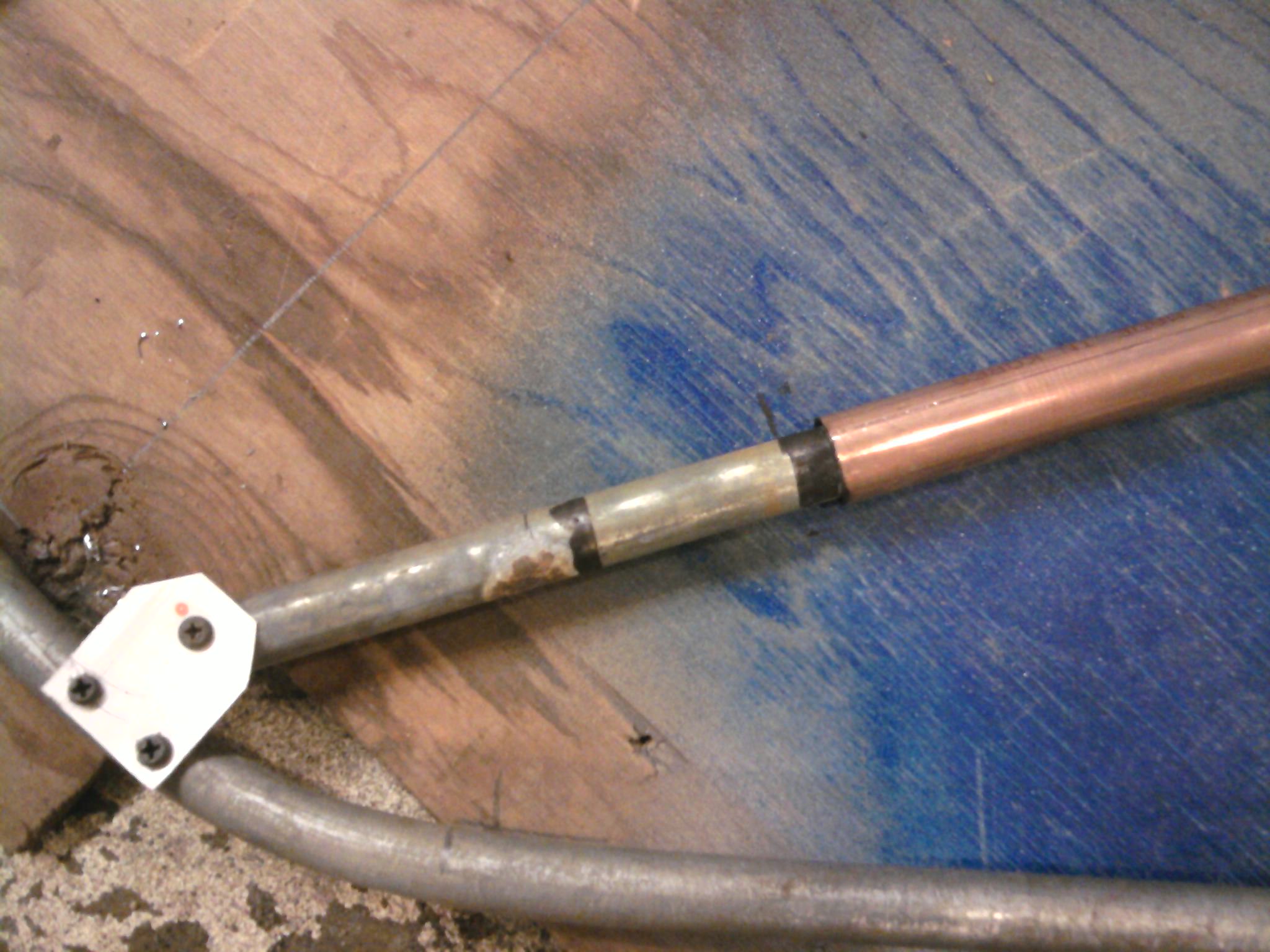
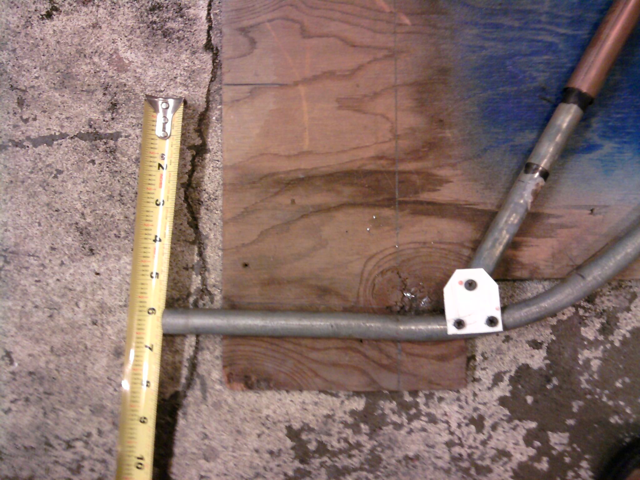
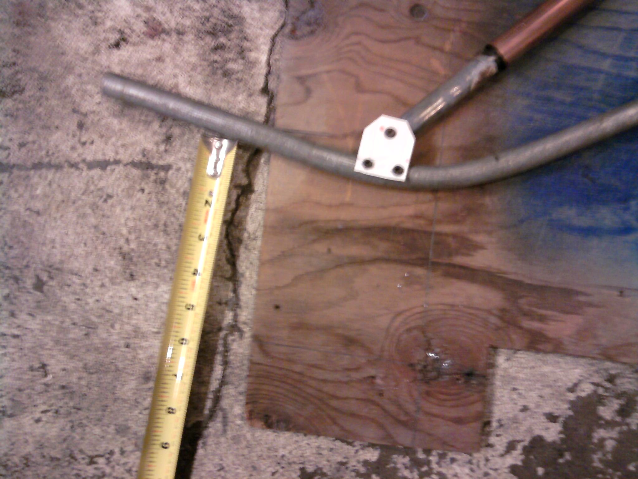
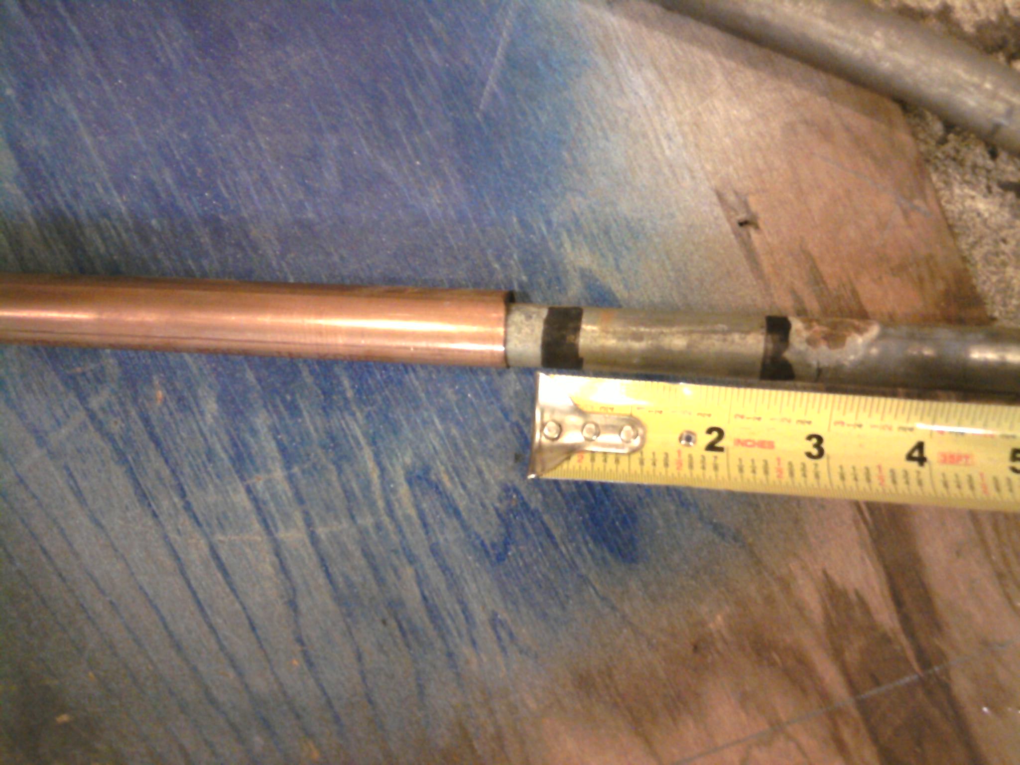
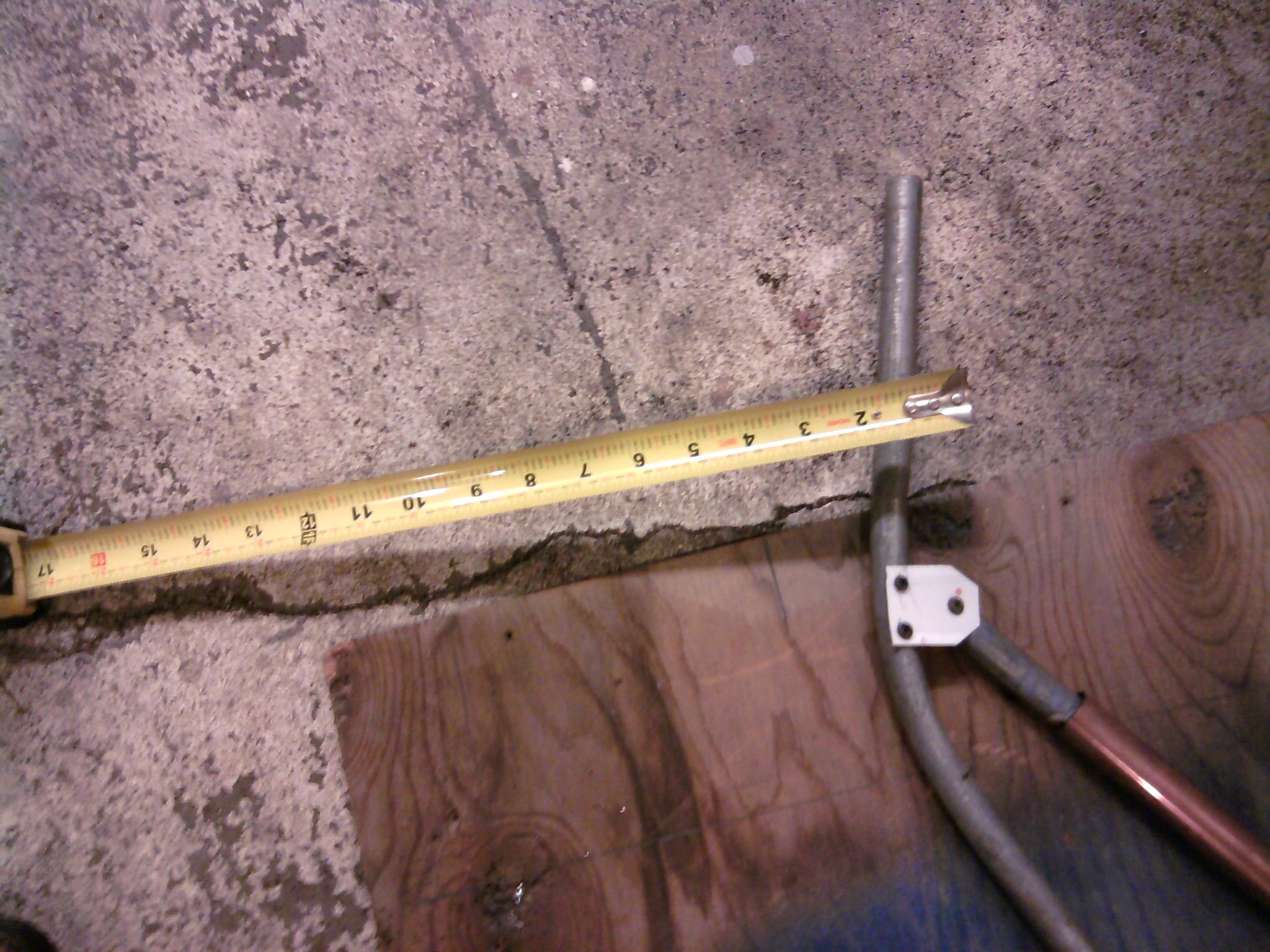
Made a bit of a mock up today, to see what kind of travel one would get. I was surprised how much the wheel would move up and down with way less travel on the shock absorber leg. You can see the lines I made on the conduit that comes out of the copper tube, moving the axel up 6" only move the shock leg 2 1/2". 10" on the wheel moved the shock leg 4". In the pictures, the top of the copper tube is screwed on where the gear leg would attach on the longeron, the axel shaft fastens about 1" off center of the fuselage. I probably wont build such a thing, but maybe some one more gifted than me in the welding department might get an idea and go for it. What to use for the spring/shock absorber? Bungees would be nice, for weight, but harder to make than springs I'm guessing. You're still left with what do you do about the shock absorbshun. Any ideas? Remember, you have to be able to hook down low on the shock leg for the rear brace leg, and the spring and shock movement happen below that brace. Does than make sense? Look at how the Berlinger gear works in the video in my last post. Anyway, any thoughts? JImChuk
PS I think the nice thing about this design is it puts the force where it's always been, right up into the gear leg attachment points, and I don't think it stresses anything else really. The axle leg does pull down on the seat truss where it attaches to it, but only about 1/4 or less of the force on the wheel going up on the other side of the shock leg which becomes a fulcrum as the axel leg becomes a teter toter in a sense.


Just came across this. Ive been thinking myself for awhile about improving the landing gear I've got. I really like that Berringer gear idea. After watching Mike Pateys landing gear upgrade on Draco
I looked up King air shocks.

http://www.filthymotorsports.com/King_Air_Shocks_p/king-air.htm
The Bush gear I bought from Stace Schrader has a leg length of 28 inches and King sells a shock that's 28" long that compresses 10". Given your mockup above that travel length might be excessive (put the prop in the dirt excessive) but you might use a shorter shock and use the axel attachment to make up some of the length.
They're $300 ea so a little pricey but probably way better than some Acme aero shocks and if Mike Patey for whom money is no object would use them they must be pretty decent quality. Bush gear generally sells for around $1000 it seems, so if you can fab your own and use these shocks you still come out cheaper than buying a bungee set.
Edit:
I should add that King isn't afraid of airplanes. I emailed and asked some questions telling them what I wanted it for and they were cool about it.
They also seem willing to customize as much as is practical. I have very little knowledge of shocks but I wonder if it's possible to use the body of a shock that has the appropriate compression length and the shaft from a longer shock to make the gear leg the right length?
-
So who made the gear your putting on? Or do we have to wait for pics of the completed installation?
-
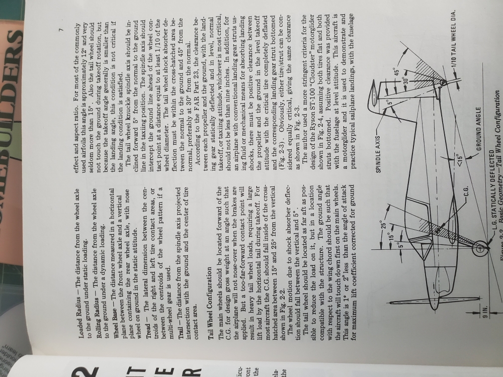
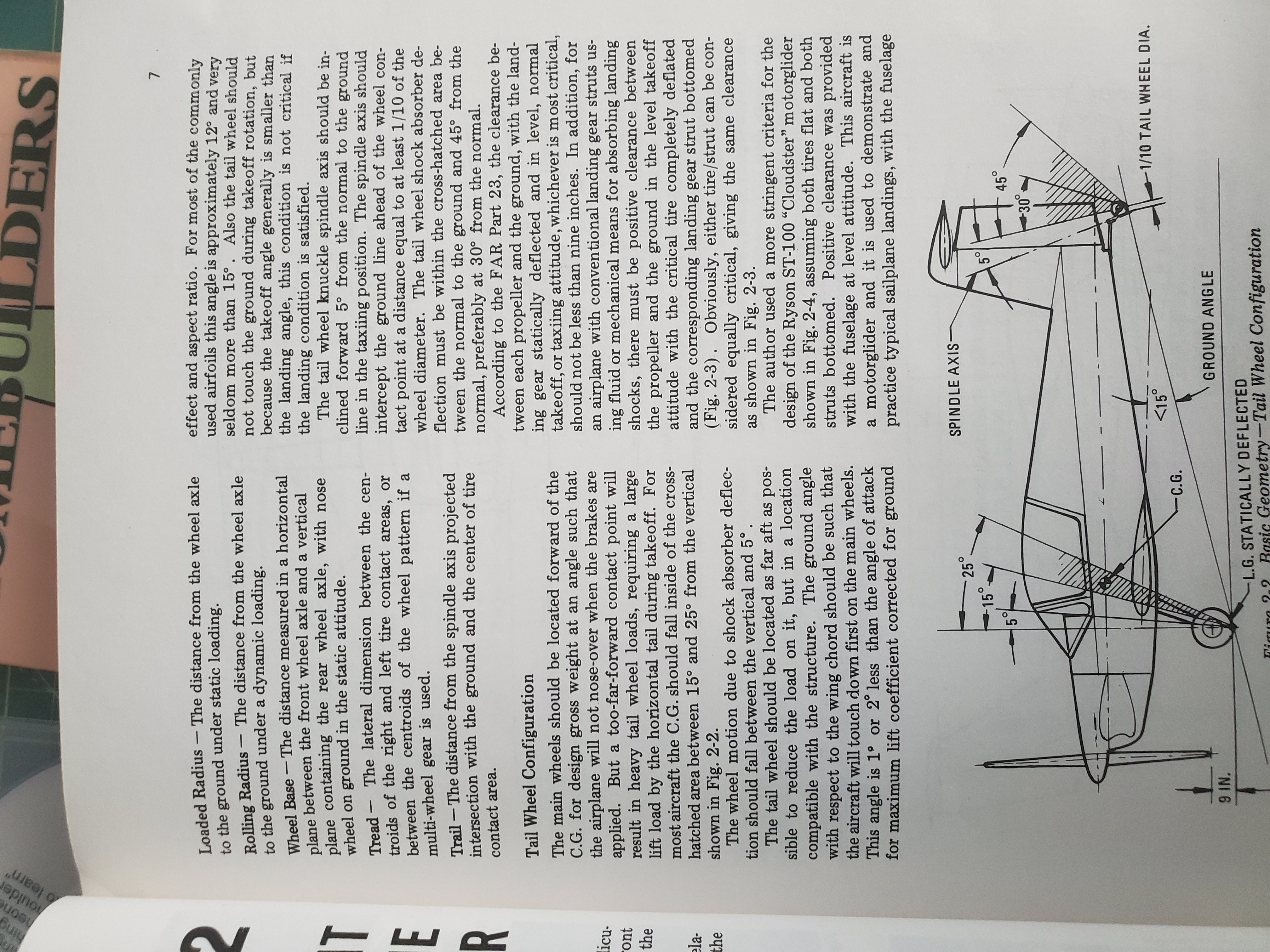
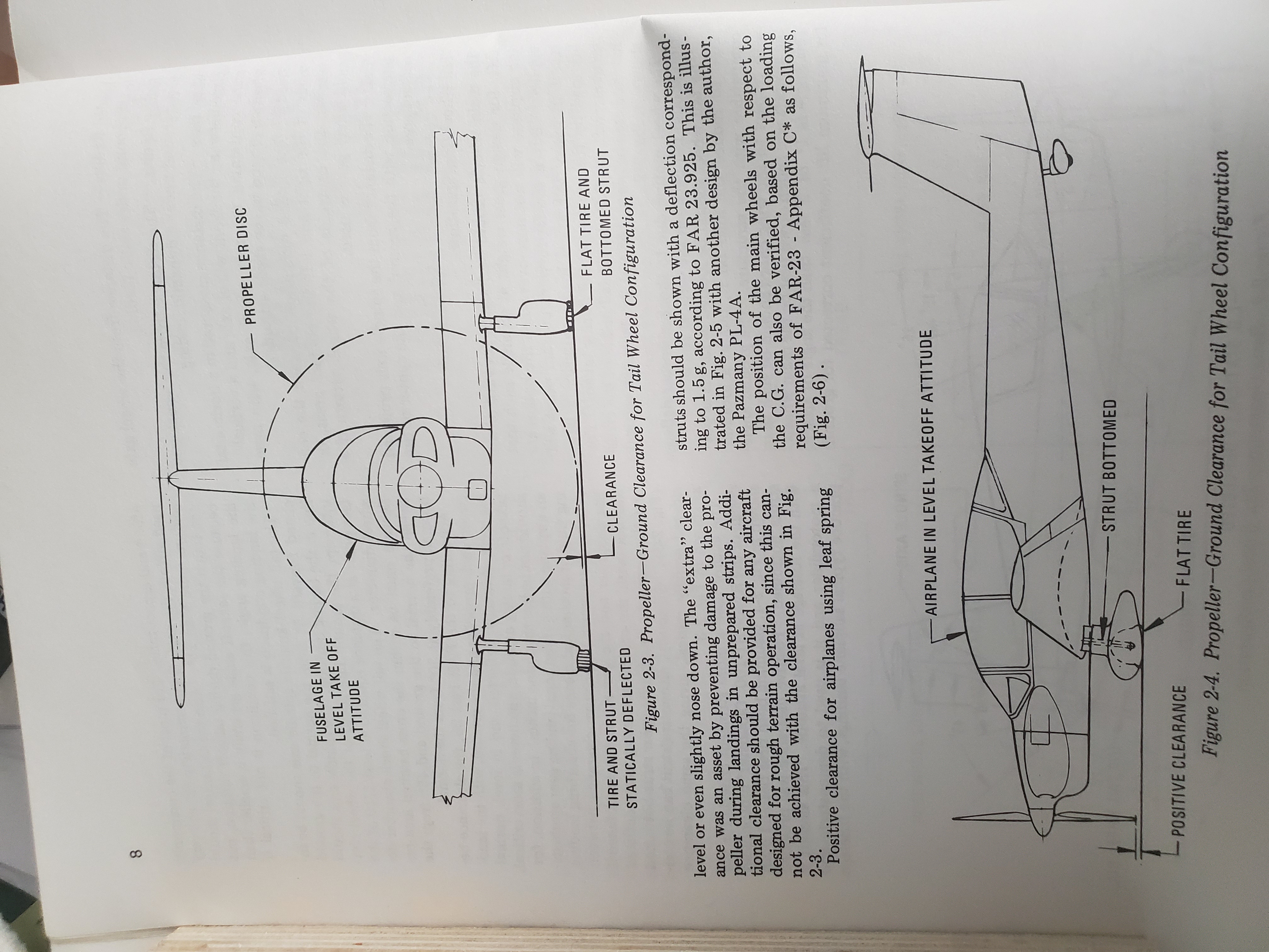
I have the book "Landing Gear Design for Light Aircraft" by Ladislao Pasmany, on page 7(attached below) he summarizes FAR 23 that says ( for certificated aircraft at least) that your minimum ground clearance with landing gear statically deflected in the takeoff position should be no less than 9". So load the plane up to max gross lift the tail to takeoff position and see how much clearance you have.
If you operate from rough strips you will want more clearance.

-
Here's a couple more videos that might give you some ideas, I looked for some videos that showed early model kitfoxs with the higher cambered wing but didn't find any with any narration. The first video below gives a couple of good warnings and he's the only guy ive seen so far that has the vgs on the skylight between the wings.
-
I asked this question above but didn't get an answer so I'll try rephrasing in multiple questions.
How much travel is there in the tailwheel on a normal landing?
How much on a "carrier" landing that doesn't damage anything(except the pilots ego)?
I'm playing around designing a different tailwheel and just wondering how much travel the standard spring gear has. How much travel is required (with the right spring etc) to avoid damage to the plane? This assumes nothing out of the ordinary. I know i could conceivably come up with a design that could take a huge beating but the rest of the plane would already have fallen apart and it would probably be way too heavy.
Here's a suggestion: Glue or sticky-tape a styrofoam block to crush when the TW spring compresses, then go out and make a few landings. First, make sure the foam doesn't rebound, or if it does, by what fraction. This way you can get the answer you seek, but nobody seems to have the answer to. The foam block needs to be thick enough that it doesn't undergo column failure, though.
that's a good idea. Unfortunately i don't have the tailfeathers on at the moment and it'll be awhile before they go back on.
I dropped mine from about 3' (uncovered) and the tailwheel flexed up approx. 1". But I have the double leaf spring so a single leaf would most likely flex 2" or more. My rudder to tail wheel clearance is 4". But I also have the stiffner plate (black plate) which spreads the load over a little more area. Wouldn't recommend anybody try dropping a single spring from 3'. I did this to test the added ears I welded on. On a light aircraft, it shouldn't be a issue, unless you really grease her in.
Thanks for the info. I didn't think there could be very much travel especially with the rudder so close. I imagine there'd be more when full of people and baggage but still not much or the rudder gets damaged.
-
1 person likes this -
Will, that is an older video. After he filmed that one, Trent glued a whole bunch of foam on his leading edge, as he promised, and found it did squat. He ripped it off because it cost him gobs of performance.
Here is the story of his leading edge experiment:
You need to be a little more careful reading and listening. They were talking in the video i posted about the Highlanders wing which according to them is the same as the early foxes. The STI wing which is on Trent's plane is an entirely different airfoil. It already has a leading edge piece of plastic or fiberglass glued to the aluminum spar. The video you linked to stated this was a new design from kitfox that hadn't been tested yet. There was some hope that there was more performance to be had. As you pointed out there's not at least with that particular design. It may also be pointed out that Trent didn't smooth the transition between the new leading edge and the rest of the wing. That could have had a significant impact.
SuberAvid has also added the KF leading edge to his plane and I don't remember specifics but I do remember he reported improved performance.
-
Was just watching Trent's video comparing his kitfox to the highlander and about 2:35 they start talking about using the kitfox leading edge on the highlander (same airfoil as the early foxes and avids). He said he got 3-5 mph speed increase on the top end and about the same in stall speed reduction. In conjunction with vgs it made a huge difference.
-
I asked this question above but didn't get an answer so I'll try rephrasing in multiple questions.
How much travel is there in the tailwheel on a normal landing?
How much on a "carrier" landing that doesn't damage anything(except the pilots ego)?
I'm playing around designing a different tailwheel and just wondering how much travel the standard spring gear has. How much travel is required (with the right spring etc) to avoid damage to the plane? This assumes nothing out of the ordinary. I know i could conceivably come up with a design that could take a huge beating but the rest of the plane would already have fallen apart and it would probably be way too heavy.
-
How much travel do you guys think these leaf springs have? I mean obviously just before impacting the rudder might be max travel but that might also be a one time thing and the next time even a soft landing might damage the rudder.
How much deflection would a normal 3 point landing cause?
-
I think the spring is sprung. Not intending to be funny, but my eye is telling me that a Kitfox spring has more of a curve to it between the fuselage and tailwheel. Also to back that up, your verticle axis of the tailwheel should be more verticle. That also says the spring is to straight. With a load on the tailwheel, the axis should be about 90 degrees to the ground. That would also give you more room between the tailwheel and the rudder. In this picture, you can see the tailspring on my Kitfox 4 after it came here from Texas. JImChuk
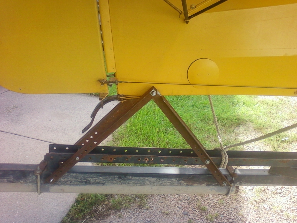
Your definitely right about the spring. 1 more thing to add to the list of things to fix. But better now than after it crunches the rudder.


Bush gear topic reopened
in Avidfoxflyers General Hangar
Posted
The whole point of this thread(as I understand it) is to explore new and different ideas. Try some out of the box thinking that might lead somewhere totally unexpected and perhaps unlikely but we just might find a better way that's never been thought of. If nothing else I think it's fun even if nothing comes of it.