
Avid Bart
Contributing Member-
Content count
82 -
Joined
-
Last visited
Posts posted by Avid Bart
-
-
Fred, Trent Palmer just stole your idea using the exact same setup! I hope you have the patent pending so you can collect your royalties.
2 people like this -
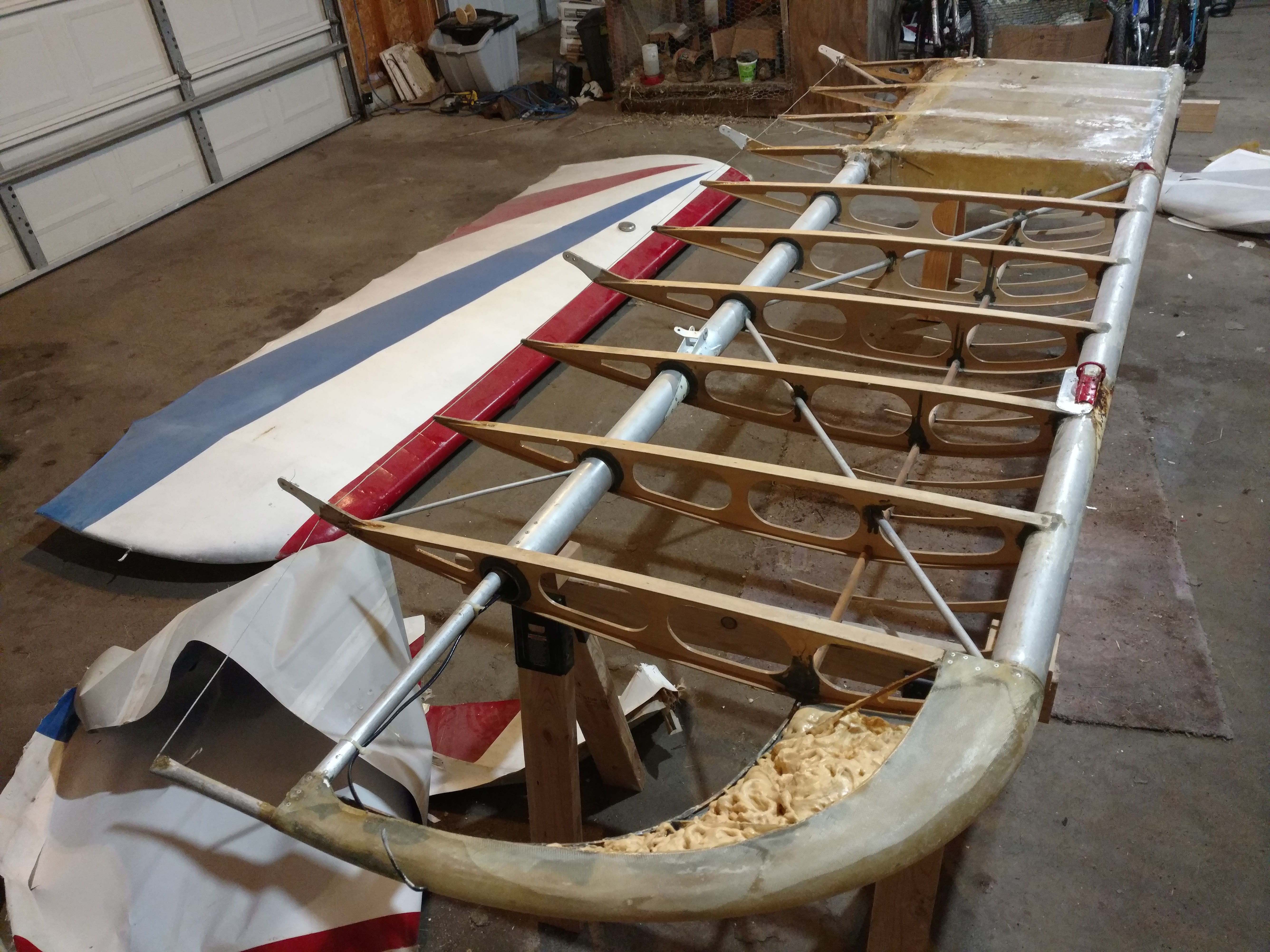
I'll try to get some pictures of my project up tomorrow, but I just finished removing the ribs from my wings and pulling fiberglass off the tanks that the builder applied. In my case, the builder did not sand the tanks and the top fiberglass pulled up easily but the fiberglass was adhered very well to the spars and bottoms of the tanks.
Pulling the ribs off is fairly easy but plan on them not being usable and making a whole new set. The Hysol epoxy softens with a heat gun and I used a sharp chisel to remove the epoxy while being careful not to damage the spars.
I am not able to see your photos right now but if you're worried about the insides of your tanks, there is a website where someone cut and removed the tops of the tanks and coated the insides with epoxy. They then re-fiberglassed the tank tops back on. I'll see if I can find a link to that site.
Here is the link to that site:
1 person likes this -
It has the offset vertical stabilizer. Didn't all model IV's come with the straight tail?
-
I found a source for 2.5" diameter 0.083" wall tubing and they would be happy to sell you 13' 6" lengths. Unfortunately, they charge $4,432 for an 8' length

https://www.twmetals.com/catalog.html?cid=tube-aluminum&id=44887-8
I was thinking maybe they have the decimal in the wrong place, but all of their prices are that high. They cater to the aerospace industry, so maybe that's the going rate for their customers.
-
You guys made me curious what the markings on the spars mean. Some of the markings on my spars are not legible. I tried piecing as much of the writing together and here is what I came up with:
ALCOA 6061-T6 WW-T-700/6 AMS-4082 ASTM-B210
The 6061-T6 is the alloy and temper
WW-T-700/6, AMS-4082, and ASTM-B210 are standards that cover aluminum drawn seamless tubing
I agree with Jim that the extruded tubing would probably be fine, but the factory used drawn seamless tubing and the cost difference is not that significant. I wouldn't take the chance on the cheaper tubing.
1 person likes this -
I am also looking for tubing to extend my spars. From what I have found, the tubing is available as extruded or drawn. Both types are extruded, but the drawn is pulled through a die which increases the strength and makes the tubing more uniform and straight. I will be going with the drawn tubing for my extensions.
2 people like this -
A guy in the EAA chapter I was in had a Viking 110 in a Sonex that he was building. He was really excited about the engine and was saying the Viking 130 has even more power with similar weight. As Ronin commented though, I think the disadvantage is weight. Isn't the 912 bare engine weight closer to 130 lbs?
-
By the way, the planes are looking great!
1 person likes this -
Ok, the next problem is how are you going to decide which one to fly?
-
The diagram shows the correct way to wire it. I was thinking you were intending to measure the return current through the fuselage to the battery, and that is why the ground wire was connected to the shunt.
Whatever you do, make sure you protect that positive battery lead. Unfused wires make great arc welders.
-
Looks like something I would do, but I wouldn't post a picture of it for the world to see
") 1 person likes this
1 person likes this -
Yep. There is no voltage drop across the shunt the way the it is wired. Your fuselage ground should go to the shunt terminal on the right and the battery negative should be connected to the shunt terminal on the left.
-
If you zoom in on the first picture, you can see the cable going through the top of the rib tail. It looks like the aluminum tube in the trailing part of the wing tip bent up and in. He might be able to bend the tube back down but if it bent in as well, there will be less tension on the wire and the whole wing trailing edge will be floppy. He will definitely need to check that before flying again.
-
Here is a picture of the inside of my wingtip. There is also a builders manual in the files section that might help.
You might be able to bend the tip down and reshrink the fabric, like TJay said.

-
Drum roll...

-
His push pull tube guides look just like my Model C's guides. I believe the factory used pieces of polyethylene plastic for bushings and a soldering iron to melt the ends to keep the bushing from sliding out. My Model C is also missing some of the bushings. I was thinking about cutting chunks of shampoo bottle and slipping it in with the push pull tube in place.
My Bandit has the larger diameter guides like what dholly shows in his pictures. I didn't realize the bushings were made out of threaded PVC pipe though.
-
Birddog, that's exactly what I had in mind. Thank you for the info!
I have a wing with a bent spar that I can use for the splices but I didn't have the details on how big the splice needed to be. Now I need to see if I can find a local source for some .083 tubing for the spar extensions and I will be set.
One more question - Did you increase the wingspan to the standard Avid span or did you go with the longer Kitfox wingspan?
-
Two things I initially took from this video: this guy has ADD, and an oil injector pump failure sent a rod through his block.
After 10 minutes or so of babbling, he explains the cause of the engine failure. The engine was previously starved of oil from someone not purging the air out of the oil pump. Like I have heard others say, these engines are murdered...
-
I highjacked another thread a while back and thought it would be best to start a new thread to ask for input. The plane I am working on has an aerobatic speedwing that I would like to extend to either the standard Avid length, or possibly the longer Kitfox wingspan.
I have discussed this a little with Jim and he had a good idea to use the I beam stiffeners that are available from Just Aircraft as internal splices. I think this would probably work well but I am also thinking about using pieces of old heavy hauler spar that I already have to make internal splice sleeves. What I am thinking is to cut a notch in the length of the spar splice piece so it will slightly collapse and fit inside the spar and then rivet through the spar and the wing extension into the splice sleeve.I remember seeing in an Avid builders manual they did something like this from the factory, I believe on the Magnum and Catalina spars. Does anyone have any details on this like the length and thickness of the spar splice sleeve and the number and spacing of the rivets?
-
It is amazing how many are unfinished or neglected and no longer airworthy. There are a lot of good projects turning up and the nice thing is they usually sell fairly cheap.
By the way, this Craigslist post was deleted so hopefully the Kitfox is going to a good home.
1 person likes this -
Good to hear you tore into it! Now you're on the path to remorse after you spend a day unsuccessfully trying to repair a $0.60 part
Honestly though, good luck fixing it. Hopefully you are able to make it work.
-
Jim, I don't think anyone is sick of your posts. I like seeing your progress, even if I am a little envious of the pace you are able to keep
Keep up the good work and keep those pictures coming!
2 people like this -
That's a nice looking plane. Looks right at home on the grass strip. I bet you're having a blast.
-
Can you print it as a PDF and delete the pages? That might preserve the quality of the document and be easier than printing and scanning. I can also take a look at it when I return to "work" on Monday.
What connector for radio cable?
in Avidfoxflyers General Hangar
Posted
You could use male and female 50 ohm BNC connectors. Just make sure they are listed to work with the type of cable that your antenna cable is made from.
Here is a connector that works for RG 142 coax cable
https://www.amazon.com/Eightwood-10pcs-Female-Connector-LMR195/dp/B074167HK8/ref=mp_s_a_1_2_sspa?keywords=rg142+bnc&qid=1554261050&s=gateway&sr=8-2-spons&psc=1
You will also need a crimp tool like this
https://www.amazon.com/rmsdeal77-Connector-Crimping-RG-174-Connectors/dp/B00LV5V17E/ref=mp_s_a_1_fkmrnull_2_sspa?
A little heat shrink tubing also helps to provide a strain relief and makes the connector look professional.